
Powering device with annular conductive rails

A technology for conducting rails and power taking devices, which is applied to circuits, current collectors, electrical components, etc., can solve the problems of low reliability, poor safety performance, and high maintenance costs, and achieve the effect of improving safety.

Inactive Publication Date: 2014-01-29
YICHANG SENDE ELECTRICAL EQUIP MFR
View PDF0 Cites 4 Cited by
  • Summary
  • Abstract
  • Description
  • Claims
  • Application Information

AI Technical Summary

Problems solved by technology

When rotating, the power cord is bent and dragged back and forth, which is prone to entanglement and is torn off. It has low reliability, poor safety performance, and high maintenance costs.

Method used


Image

  • Powering device with annular conductive rails

Examples


Embodiment Construction

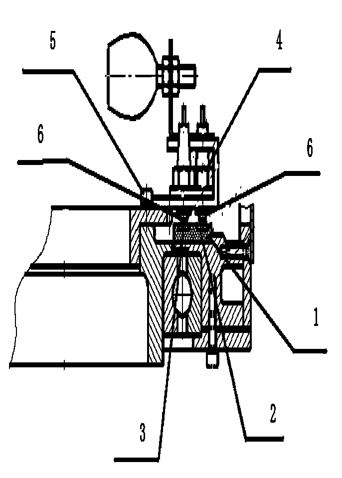
[0013] Such as figure 1 Among them, the power-taking device of the ring-shaped conductive track of the analog positioning machine light field lamp includes an outer ring conductive track 2, an inner ring conductive track 3, an insulating substrate 1, and a brush 4; the outer ring conductive track 2 and the inner ring conductive track 3 are respectively arranged on the insulating substrate 1, there is a certain distance between the outer ring conductive track 2 and the inner ring conductive track 3; the brush 4 is fixed on the brush bracket 5, and the brush 4 has two brush heads 6, and the two brush heads 6 are respectively connected to the outer ring The conductive track 2 and the inner ring conductive track 3 are connected; the brush holder 5 is above the insulating substrate 1 .

[0014] Working principle of the present invention: when working, the power supply is connected to the outer ring conductive track 2 and the inner ring conductive track 3, and the brush 4 fixed to t...


PUM


Abstract

The invention discloses a powering device with annular conductive rails. The powering device comprises an outer-ring conductive rail (2), an inner-ring conductive rail (3), an insulating base plate (1) and an electric brush (4); the outer-ring conductive rail (2) and the inner-ring conductive rail (3) are respectively arranged on the insulating base plate (1) and are separated from each other by a certain distance; the electric brush (4) is fixed onto an electric brush support (5) and is provided with two brush heads (6), and the two brush heads (6) are respectively connected with the outer-ring conductive rail (2) and the inner-ring conductive rail (3). The powering device has the advantages that the two annular conductive rails are used for transmitting power, easy breakage of the power transmission device due to repeated bending and dragging when a machine rotates around a certain point or a plurality of points can be prevented, and accordingly the reliability and the safety can be improved.

Description

technical field [0001] The invention relates to a power transmission device, in particular to a ring-shaped conductive track power-taking device. Background technique [0002] Existing rotating machinery, especially the light fields of analog positioning machines and accelerators, generally adopt the power line transmission method. The specific method is that one end of the power line rotates with the machine, and the other end is fixed on the power supply, and a certain length should be left for the movable part in the middle. , to meet the needs of optomechanical rotation. When rotating, the power cord is bent and dragged back and forth, which is prone to entanglement and is torn off, which has low reliability, poor safety performance, and high maintenance costs. Contents of the invention [0003] The technical problem to be solved by the invention is a device for improving the reliability and safety of the power transmission equipment when the machine is rotating. [...

Claims


Application Information

Patent Timeline
IPC IPC(8): H01R39/64
Inventor 周尤刚刘森
Owner YICHANG SENDE ELECTRICAL EQUIP MFR
Learn More