Liftable transfer trolley with metal armored movable switchgear

A switchgear and metal armoring technology, which is applied in the field of liftable transfer trolleys, can solve the problems of reduced work efficiency, cost increase, deviation, etc., and achieve the effects of saving costs, improving work efficiency, and reducing the number of uses

Inactive Publication Date: 2014-02-05
SHANGHAI NAJIE COMPLETE SETAB OF ELECTRIC
View PDF8 Cites 3 Cited by
  • Summary
  • Abstract
  • Description
  • Claims
  • Application Information

AI Technical Summary

Problems solved by technology

[0002] At present, the lower handcart of the metal armored switchgear often adopts a non-lifting transfer trolley, especially when the cabinet is installed on site, channel steel may be embedded or channel steel may be laid on the original foundation plane due to different installation habits, and due to the After the body is installed, there will be deviations between the basic installation size of the cabinet and the actual theoretical value. Therefore, the height of the common transfer trolleys cannot be adjusted, and it is necessary to convert trolleys of different heights on site, which reduces work efficiency and increases costs.

Method used


Image

  • Liftable transfer trolley with metal armored movable switchgear
  • Liftable transfer trolley with metal armored movable switchgear
  • Liftable transfer trolley with metal armored movable switchgear

Examples


Embodiment Construction

[0028] The preferred embodiments of the present invention are given below in conjunction with the accompanying drawings to describe the technical solution of the present invention in detail.

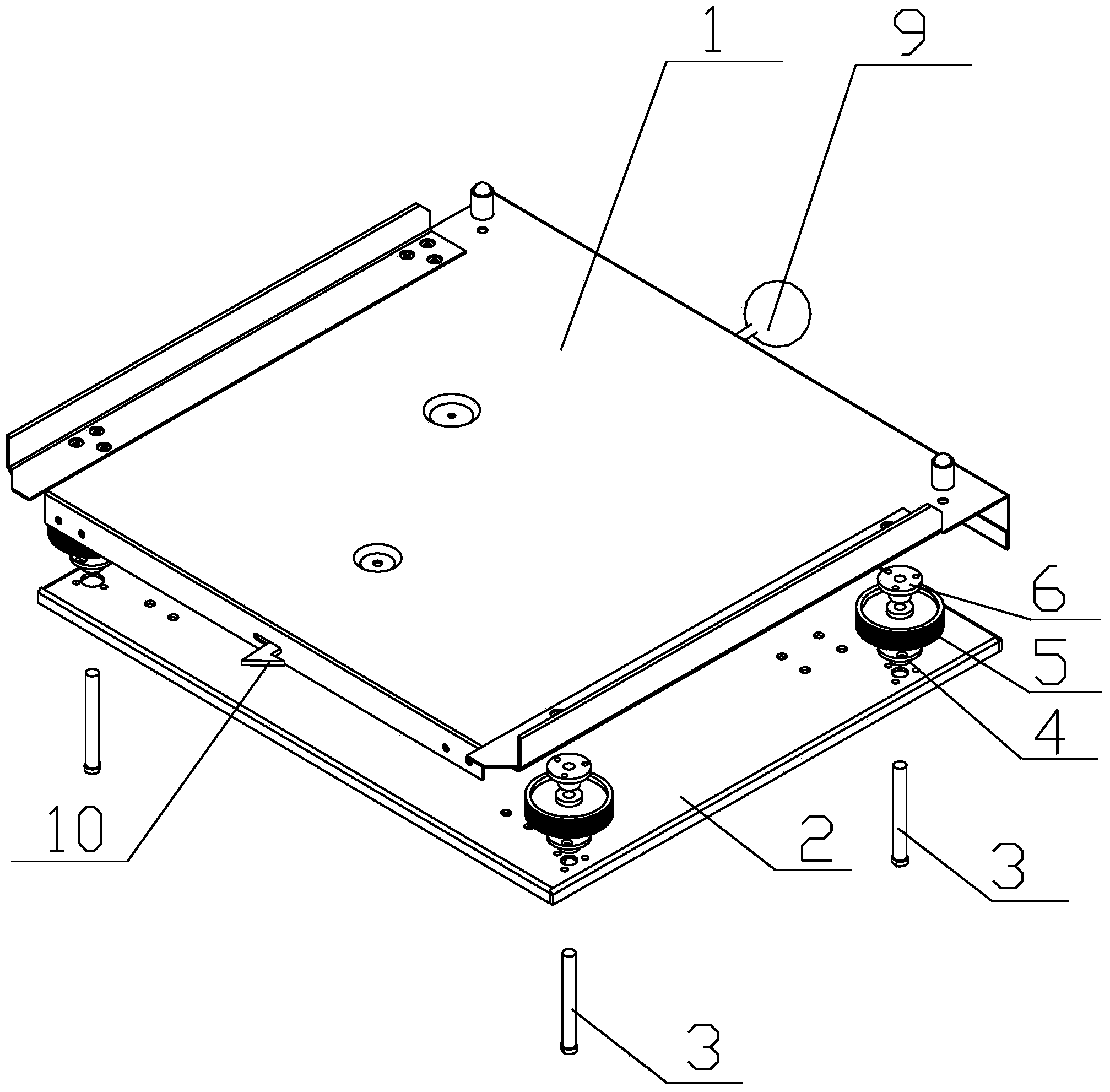
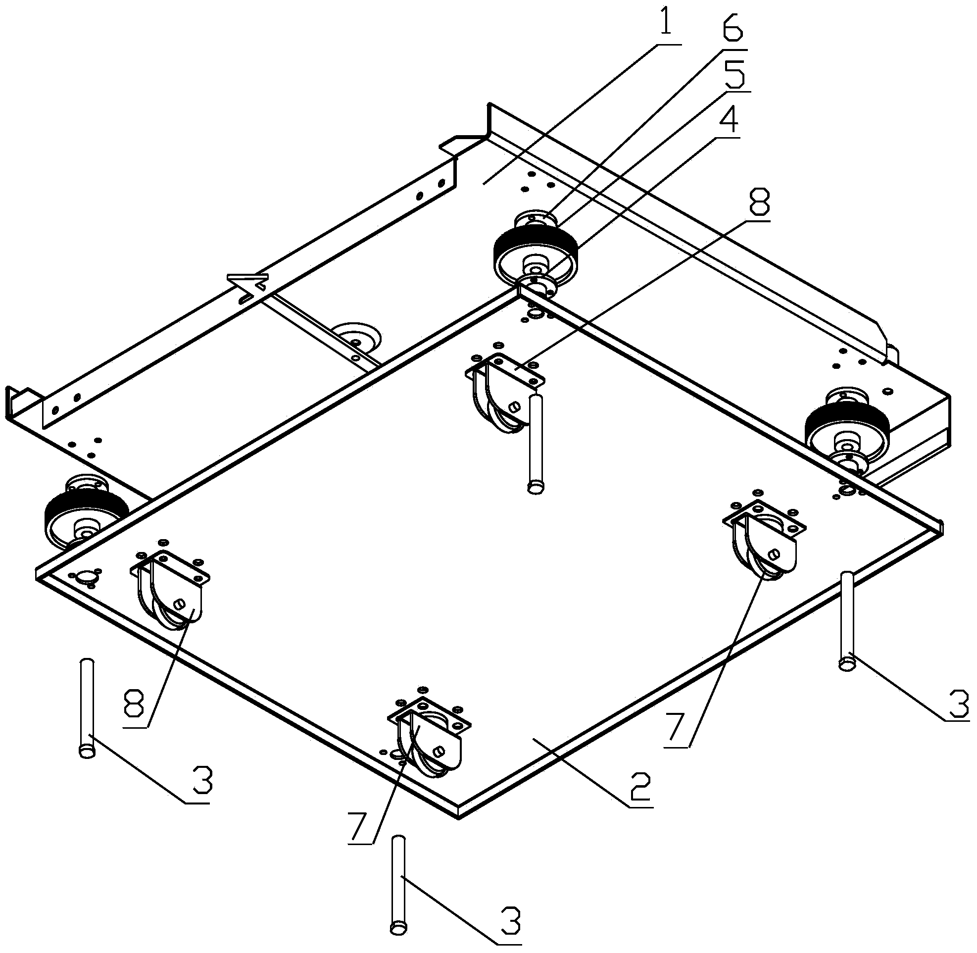
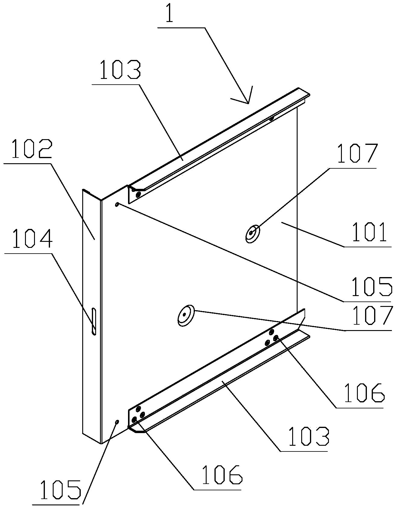
[0029] figure 1 It is one of the schematic diagrams of the three-dimensional structure of the liftable transfer trolley equipped with metal armored removable switchgear provided by the present invention, figure 2 The second schematic diagram of the three-dimensional structure of the liftable transfer trolley equipped with metal armored removable switchgear provided by the present invention. Such as Figure 1-2 As shown: the liftable transfer trolley equipped with metal armored removable switchgear provided by the present invention includes a supporting plate 1, a bottom plate 2 and a liftable mechanism between the supporting plate 1 and the bottom plate 2, and the lifting mechanism includes: a A lifting screw 3 that adjusts the lifting and is provided with external threads; a screw po...


PUM


Abstract

The invention relates to a liftable transfer trolley with a metal armored movable switchgear. The liftable transfer trolley with the metal armored movable switchgear comprises a supporting plate, a base plate and liftable mechanisms. Each liftable mechanism comprises a lifting threaded rod, a threaded rod locating sleeve of each lifting threaded rod, a lifting rotary disk and a threaded rod fixing sleeve, wherein each lifting threaded rod can carry out adjustable lifting, and is provided with external threads, each lifting rotary disk is arranged on the corresponding lifting threaded rod in a tightly sleeved mode, each threaded rod fixing sleeve comprises internal threads, and is connected with the corresponding lifting threaded rod, the threaded rod locating sleeves are fixed to the base plate, and the threaded rod fixing sleeves are fixed to the supporting plate. Each lifting threaded rod penetrates through a lifting threaded rod through hole formed in the base plate, the corresponding threaded rod locating sleeve and the corresponding lifting rotary disk, the end, close to the supporting plate, of each lifting threaded rod is fixed to the corresponding threaded rod fixing sleeve through the threads, the internal threads of each threaded rod fixing sleeve are used in cooperation with the external threads of the corresponding lifting threaded rod, and when the height of the liftable transfer trolley needs to be adjusted, the lifting rotary disks are manually rotated. According to the liftable transfer trolley with the metal armored movable switchgear, due to the fact that the liftable mechanisms are used for carrying out ascent and descent on the trolley arranged below a metal armored switch cabinet according to the requirement on the site, working efficiency is improved, and cost is reduced.

Description

technical field [0001] The invention relates to a transfer trolley, in particular to a liftable transfer trolley equipped with metal armored removable switchgear. Background technique [0002] At present, the lower handcart of the metal armored switchgear often adopts a non-lifting transfer trolley, especially when the cabinet is installed on site, channel steel may be pre-embedded or channel steel laid on the original foundation plane due to different installation habits, and due to the After the body is installed, there will be deviations between the basic installation size of the cabinet and the actual theoretical value. Therefore, the height of the common transfer trolleys cannot be adjusted, and it is necessary to convert trolleys of different heights on site, which reduces work efficiency and increases costs. Contents of the invention [0003] In view of the above problems, the main purpose of the present invention is to provide a liftable transfer trolley equipped w...

Claims


Application Information

Patent Timeline
Patent Type & Authority Applications(China)
IPC IPC(8): H02B11/167
Inventor 李纪平
Owner SHANGHAI NAJIE COMPLETE SETAB OF ELECTRIC
Why Eureka
Try Eureka