An inverted track sliding system and sliding method thereof

An inverted track technology, applied in the direction of track, movable track, road, etc., can solve the problems that the track cannot be completely laid, and the overall slip cannot be realized, so as to achieve the effect of two-way slip

Active Publication Date: 2015-09-09
JIANGSU HUNING STEEL MECHANISM
View PDF4 Cites 0 Cited by
  • Summary
  • Abstract
  • Description
  • Claims
  • Application Information

AI Technical Summary

Problems solved by technology

[0002] The application of sliding construction technology in the field of steel structure construction is increasing, but for high-altitude curved or high-altitude straight buildings, the general sliding construction technology cannot be realized, because high-altitude curved or high-altitude straight buildings cannot be completely laid due to the limitation of high-altitude conditions track, unable to achieve overall slippage

Method used


Image

  • An inverted track sliding system and sliding method thereof
  • An inverted track sliding system and sliding method thereof

Examples


Embodiment

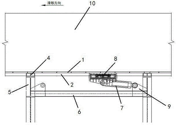
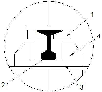
[0021] An inverted rail sliding system as shown in the figure includes: rail pressing plate 1, moving rail 2, sliding block 3, support frame 5, fixed base 6, crawler 7, rail clamp 8, connecting lug plate 9.

[0022] The connection relationship of the above components is as follows:

[0023] There are at least two support frames 5; the fixed base 6 is fixed between two adjacent support frames;

[0024] The slide block 3 is located on the top of the support frame 5, and the upper surface of the slide block 3 is provided with a sliding guide groove 4; the track pressing plate 1 is installed under the sliding box 10; the track pressing plate 1 buckles the moving rail 2 The upper end is fixedly connected to it; the lower end of the movable rail 2 is located in the guide groove 4 to support the sliding box 10; one end of the crawler 7 is fixed on the fixed base 6, and the other end is connected to the rail clamp 8 The bottom end is connected, the upper end of the rail clamp 8 clamps the ...


PUM


Abstract

The invention discloses a back-off-type rail sliding system. The number of supporting frames is at least two, a fixing base is fixed between the two adjacent supporting frames, a sliding block is located at the top of each supporting frame, and a sliding guide groove is formed in the upper surface of each sliding block. A rail pressing plate is installed below a sliding box body, buckled with the upper end of a movable steel rail and fixedly connected with the movable steel rail, and the lower end of the movable steel rail is located in the guide grooves to support the sliding box body. One end of a crawl device is fixed on the fixing base, the other end of the crawl device is connected with the bottom end of a rail clamping device, and the upper end of the rail clamping device clamps the lower end of the movable steel rail located between the adjacent supporting frames. The back-off-type rail sliding system and a sliding method of the back-off-type rail sliding system are suitable for high-attitude linear or high-attitude curve sliding, and resolve the problem that the rail can not be laid completely due to the limitation of the high-attitude condition.

Description

Technical field [0001] The invention relates to an inverted track sliding system used in steel structure construction and a sliding method thereof. Background technique [0002] There are more and more applications of sliding construction technology in the field of steel structure construction, but for high-altitude curved or high-altitude linear buildings, the general sliding construction technology cannot be achieved because high-altitude curved or high-altitude linear buildings cannot be completely laid due to high-altitude conditions. The track cannot achieve overall slippage. Summary of the invention [0003] The purpose of the invention is to provide an inverted track sliding system and a sliding method suitable for high-altitude straight or high-altitude curves in view of the deficiencies in the prior art. [0004] Technical solution: In order to achieve the above objective, the present invention provides an inverted rail sliding system, including: a rail pressing plate, a m...

Claims


Application Information

Patent Timeline
Patent Type & Authority Patents(China)
IPC IPC(8): E04G21/16E01B23/10
Inventor 丁剑强吴文平刘远帆严擒龙刘华蒋飞
Owner JIANGSU HUNING STEEL MECHANISM
Why Eureka
Try Eureka