Visual pelvic floor puncture device and auxiliary equipment thereof

An auxiliary device and pelvic floor technology, which is applied in the direction of puncture needles, puncture needles, and other medical devices, to achieve accurate surgical results, easy operation, and improved convenience

Pending Publication Date: 2020-03-27
重庆市妇幼保健院
View PDF2 Cites 3 Cited by
  • Summary
  • Abstract
  • Description
  • Claims
  • Application Information

AI Technical Summary

Problems solved by technology

However, this technique is only effective when the puncture device is taken out. During the puncture process, medical staff need to judge the puncture position based on experience, and the essence of blind puncture remains unchanged.

Method used


Image

  • Visual pelvic floor puncture device and auxiliary equipment thereof
  • Visual pelvic floor puncture device and auxiliary equipment thereof
  • Visual pelvic floor puncture device and auxiliary equipment thereof

Examples


Embodiment 1

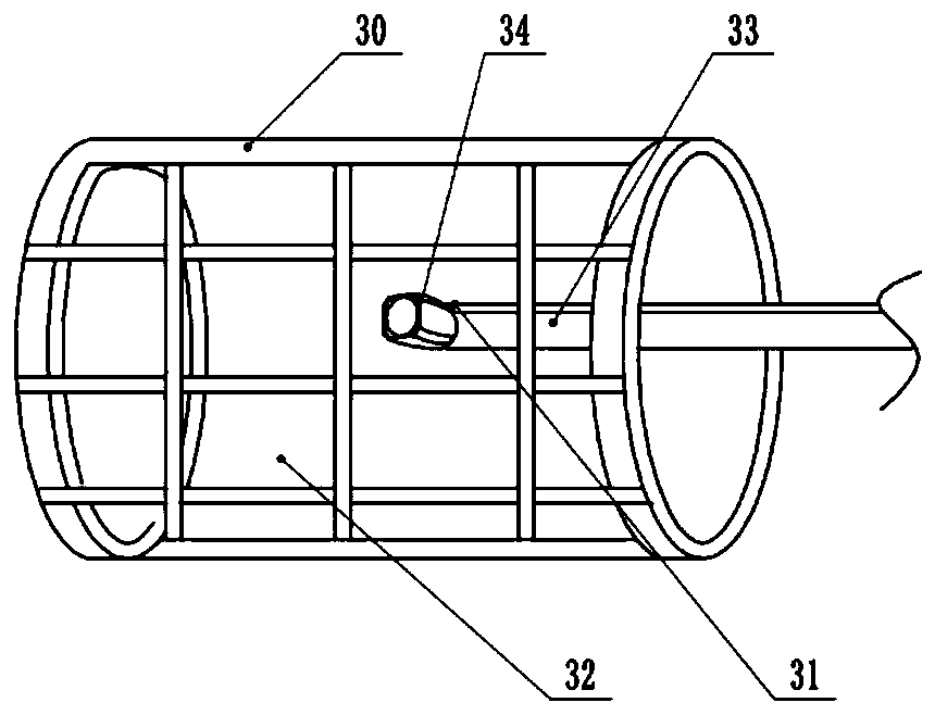
[0047] Please refer to figure 1 , a visual pelvic floor puncture aid, including a fixed cylindrical sleeve 30 for supporting and a visual operation kit for observing the pelvic floor, the inside of the sleeve 30 is equally divided into several hollow grids 32, Grids 32 are equidistantly spaced, and a mirror sheath 33 loaded with a visual operation kit passes through the grids 32, and the visual manipulation kit includes an endoscope 34 and a display endoscope located inside the mirror sheath 33. 34-image display. The endoscope 34 includes a lens and brackets 31 hinged on both sides of the lens, and an operating module for controlling the swing of the lens is provided at the rear end of the lens.

[0048] Please refer to Figure 5 The operation module and the signal are connected to the control module that converts the electrical signal and the analog signal, the control module is built in the display screen, and the display screen is connected with an input device that drive...

Embodiment 2

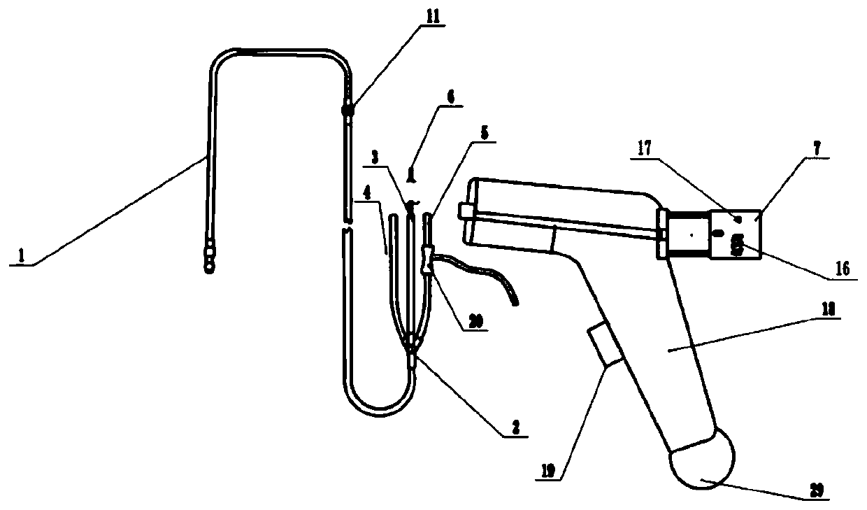
[0051] The difference between this embodiment and the above embodiment is that, adding a visual pelvic floor puncture device, it is basically as attached figure 2 As shown: a visualized pelvic floor puncture device includes a handle 18 for holding and a drainage tube 1 for flushing, and the drainage tube 1 is inserted into the handle 18;

[0052] The drainage pipe 1 includes a water inlet end and a water outlet end, a set of joints 11 are bonded between the water inlet end and the water outlet end, a through valve 20 is set on the water outlet end, and a four-way pipe 2 and a four-way pipe 2 are connected to the entrance of the water inlet end. The puncture tube 3, the pressure outlet tube 4 and the pressure collection tube 5 are connected at the port of the four-way pipe. The last port of the four-way pipe 2 is connected to the water inlet end of the drainage tube 1. same side.

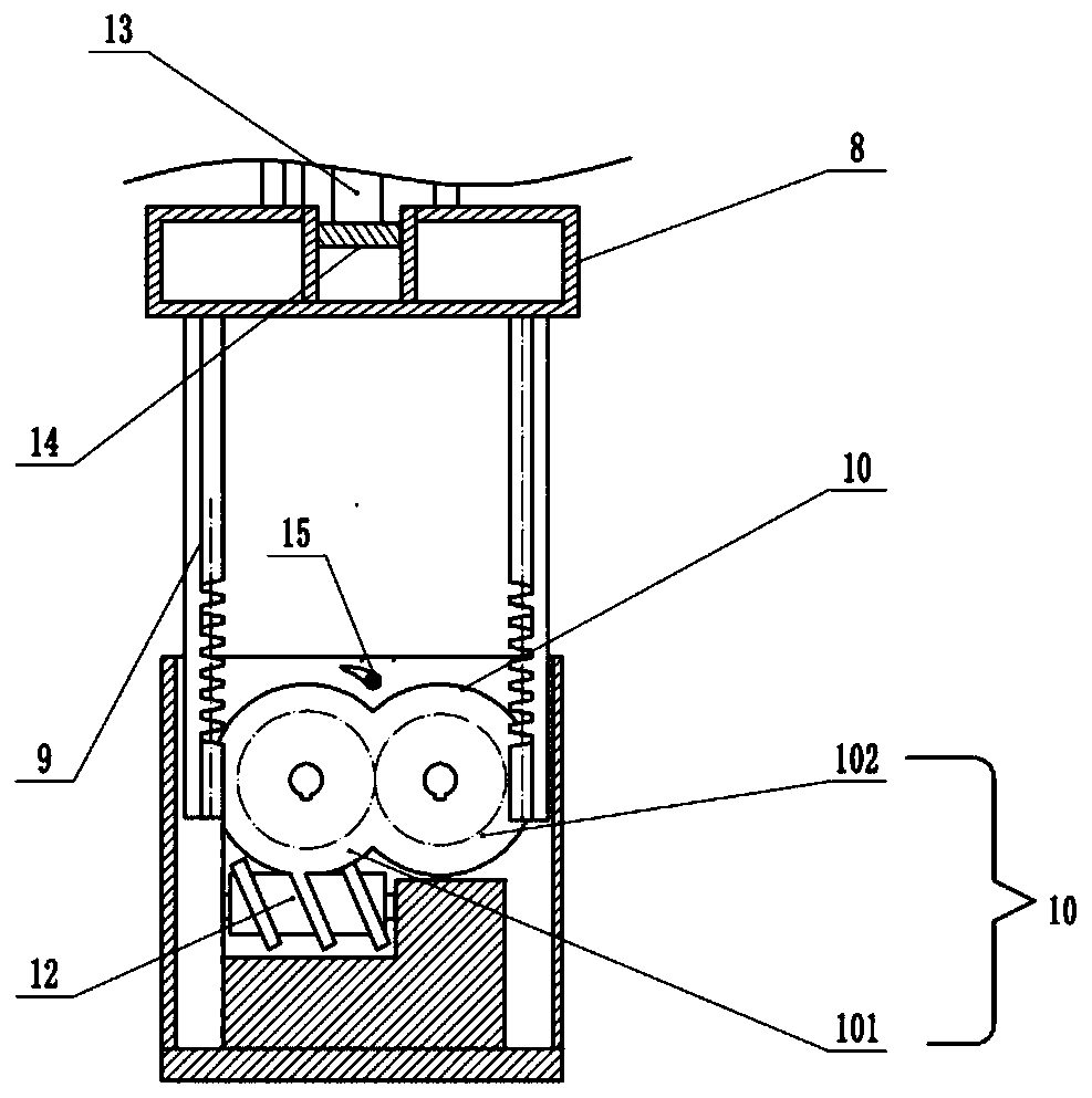
[0053] Please refer to image 3 , a puncture needle 13 is placed in the puncture tube 3, and t...


PUM


Abstract

The invention discloses a visual pelvic floor puncture device and auxiliary equipment thereof in the field of medical instruments, and aims to reduce the risk that blood vessels, nerves and surrounding important organs are damaged by blind puncture in the current vaginal pelvic floor reconstruction (TVM) operation process. The device comprises a cylindrical transparent sleeve for supporting a lacuna space, an internal camera shooting component and a visual system connected with the outside for observation, wherein the outer surface of the sleeve is divided into a plurality of fine hollow grids; a mirror sheath of a visual operation kit is fixed in the center of a base in the sleeve; and the visual operation kit comprises an endoscope positioned in the mirror sheath and a high-definition display screen for displaying an endoscope image. Compared with the traditional TVM operation process, the visual pelvic floor puncture device has the advantages that blind puncture is converted into visual puncture, so that the puncture part is more accurate, the operation effect is more exact, and the risk of damage to blood vessels, nerves and surrounding important organ tissues caused by blind puncture can be greatly reduced; and the device is integrally designed, is simple and convenient to operate, does not need carbon dioxide to establish pneumoperitoneum, is low in cost and can be disinfected and repeatedly used.

Description

technical field [0001] The invention belongs to the field of medical instruments, in particular to a visualized pelvic floor puncture device and its auxiliary equipment. Background technique [0002] Female pelvic floor dysfunction is a common disease among middle-aged and elderly women, which seriously affects the quality of life of patients. The current research on this type of disease has formed a new discipline, namely gynecological urology and female pelvic floor reconstruction surgery. At present, there are more than 100 surgical methods based on the basic theory of the pelvic floor, among which vaginal pelvic floor reconstruction is an irreplaceable and important type of pelvic floor surgery, which provides treatment opportunities for elderly patients with comorbidities. However, the blind puncture technique in vaginal pelvic floor reconstruction surgery is a key difficulty restricting its technical development. [0003] In order to solve the above-mentioned blind p...

Claims


Application Information

Patent Timeline
Patent Type & Authority Applications(China)
IPC IPC(8): A61B17/34A61M3/02A61B1/303A61B1/04A61B1/045
CPCA61B1/04A61B1/045A61B1/303A61B17/3403A61B17/3415A61B17/3478A61B17/3494A61M3/0279A61M3/0287A61M2210/1475A61M2210/005
Inventor 卢深涛刘禄斌代艳刘明博雷丽孙玉菡王荥赵成志颜丽唐春艳
Owner 重庆市妇幼保健院
Why Eureka
Try Eureka