A Two-way Sliding Pipe Support Capable of Bearing Two-way Vertical Loads

A pipe support and vertical load technology, applied in the direction of pipe supports, pipes/pipe joints/fittings, mechanical equipment, etc., can solve the problems of low friction coefficient and failure to meet the requirements of use, and achieve the effect of two-way sliding

Active Publication Date: 2016-03-23
LUOYANG SUNRUI SPECIAL EQUIP
View PDF8 Cites 0 Cited by
  • Summary
  • Abstract
  • Description
  • Claims
  • Application Information

AI Technical Summary

Problems solved by technology

[0002] figure 1 A schematic diagram of the structure of the sliding pipe support in the prior art is given; the sliding pipe support includes a lower base plate 1 and an upper base plate 5; 8 and the vertical plate 7 are welded on the upper base plate 5; two symmetrically arranged baffle plates 6 are fixed on the lower base plate 1, and the lower base plate is located between the two baffle plates 6, and the two baffle plates 6 Constrain the radial movement of the pipe. The upper slide plate 4 attached to the lower end surface of the upper base plate 5 and the polytetrafluoro slide plate 3 installed on the upper end face of the lower base plate 1 form a sliding friction pair, so that the pipe can slide along the axial direction of the pipe. The radial direction is constrained; the upper slide 4 is a mirror stainless steel slide, and the PTFE slide 3 is a PTFE slide filled with a PTFE composite interlayer slide; the sliding slide composed of a mirror stainless steel and a PTFE slide The friction pair has the advantages of low friction coefficient, wear resistance, large load capacity and reliable operation; however, the structure of the above-mentioned sliding pipe support can only bear the downward vertical load; for some special application environments, such as when the pipe support bears When the load is vertically upward, it is difficult for the currently used horizontal pipe support to meet the effect of this variable comprehensive load and cannot meet the use requirements

Method used


Image

  • A Two-way Sliding Pipe Support Capable of Bearing Two-way Vertical Loads
  • A Two-way Sliding Pipe Support Capable of Bearing Two-way Vertical Loads
  • A Two-way Sliding Pipe Support Capable of Bearing Two-way Vertical Loads

Examples


Embodiment Construction

[0017] The present invention is described in conjunction with accompanying drawing and specific embodiment:

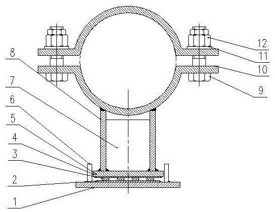
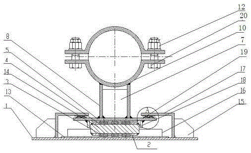
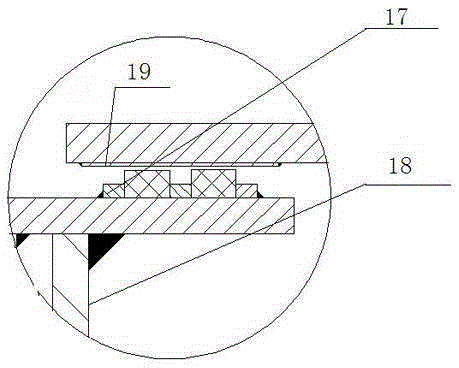
[0018] Such as figure 2 , image 3 As shown, a two-way sliding pipe support that can withstand two-way vertical loads; the two-way sliding pipe support includes a lower base plate 1 and an upper base plate 5; the upper base plate 5 is located above the lower base plate 1, on the upper A pipe is installed above the base plate 5, that is, the pipe is clamped by two half-type pipe clamps 10, and the pipe clamp 10 is fixed on the upper base plate 5 through the vertical plate 7; between the upper base plate 5 and the lower base plate 1 An intermediate plate 14 is provided; the upper and lower surfaces of the intermediate plate 14 are fixed with an orifice 2 for installing a polytetrafluoro slide 3; the polytetrafluoro slide 3 is installed in the orifice; located in the middle The sliding friction pair I is formed between the PTFE sliding plate 3 on the upper surface of t...


PUM


Abstract

The invention belongs to the technical field of pipeline system support frames and support seats, and discloses a bidirectionally-sliding pipeline support seat capable of bearing a bidirectional vertical load. The bidirectionally-sliding pipeline support seat capable of bearing the bidirectional vertical load comprises a lower base plate (1) and an upper base plate (5), wherein a slide friction pair I is arranged between the upper base plate (5) and the lower base plate (1); top plates (17) are arranged at two ends above the upper base plate (5); the top plates (17) are fixed on the lower base plate (1); a slide friction pair II is formed between a top slide plate (19) attached to the top plates (17) and polytetrafluoroethylene slide plates (3) installed at the two ends of the upper surface of the upper base plate (5); an upper baffle (18) for limiting when a pipeline slides along the axial direction thereof and a lower baffle (16) for limiting when the pipeline slides along the radial direction thereof are arranged. The bidirectionally-sliding pipeline support seat capable of bearing the bidirectional vertical load disclosed by the invention meets the application of a varied comprehensive load pipeline, and realizes the bidirectional slide of the pipeline under the bidirectional vertical load.

Description

technical field [0001] The invention belongs to the technical field of pipeline system support supports, and in particular relates to a bidirectional sliding pipeline support capable of bearing bidirectional vertical loads. Background technique [0002] figure 1 A schematic diagram of the structure of the sliding pipe support in the prior art is given; the sliding pipe support includes a lower base plate 1 and an upper base plate 5; 8 and the vertical plate 7 are welded on the upper base plate 5; two symmetrically arranged baffle plates 6 are fixed on the lower base plate 1, and the lower base plate is located between the two baffle plates 6, and the two baffle plates 6 Constrain the radial movement of the pipe. The upper slide plate 4 attached to the lower end surface of the upper base plate 5 and the polytetrafluoro slide plate 3 installed on the upper end face of the lower base plate 1 form a sliding friction pair, so that the pipe can slide along the axial direction of ...

Claims


Application Information

Patent Timeline
Patent Type & Authority Patents(China)
IPC IPC(8): F16L3/08
CPCF16L3/1091F16L3/16
Inventor 刘向伟张国华李德雨席辉
Owner LUOYANG SUNRUI SPECIAL EQUIP
Why Eureka
Try Eureka