Radiator structure and production method thereof

A manufacturing method and heat sink technology, applied in manufacturing tools, heat exchange equipment, lighting and heating equipment, etc., can solve the problem of incomplete tight fit, incomplete tight fit of heat dissipation fins and metal bases, separation of heat dissipation fins, etc. question

Active Publication Date: 2014-02-12
ASIA VITAL COMPONENTS SHENZHEN CO LTD
View PDF4 Cites 2 Cited by
  • Summary
  • Abstract
  • Description
  • Claims
  • Application Information

AI Technical Summary

Problems solved by technology

[0004] 2. The case of patent application No. 098220381 in Taiwan, China discloses a heat dissipation structure with combined heat dissipation fins, which mainly includes a metal base and a plurality of heat dissipation fins, and the heat dissipation fins are integrally stamped from a metal plate The fins are bent into a U shape. The heat dissipation fins include two heat dissipation parts and an elastic buckle part. The two heat dissipation parts are respectively in the shape of a flat plate. The elastic buckle part is U-shaped. The end has reset elasticity, and its two ends are fixedly connected to one end of the heat dissipation part respectively. The two ends of the elastic buckle can be pressed and close to each other, so that the elastic buckle is deformed, so that the elastic buckle The buckle can be inserted into a plurality of gr

Method used


Image

  • Radiator structure and production method thereof
  • Radiator structure and production method thereof
  • Radiator structure and production method thereof

Examples


Embodiment Construction

[0051] The above-mentioned purpose of the present invention and its structural and functional characteristics will be described according to the preferred embodiments of the accompanying drawings.

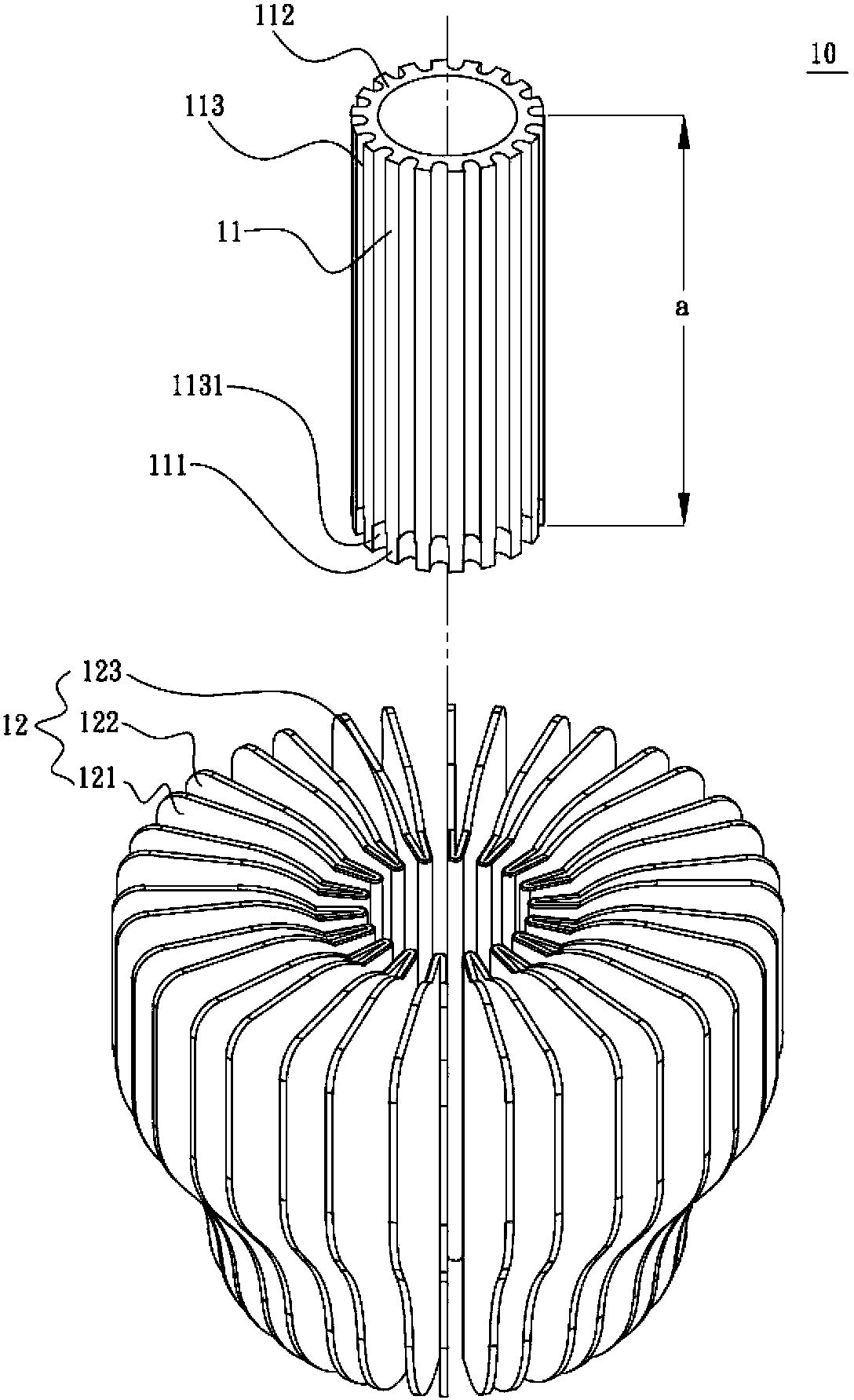
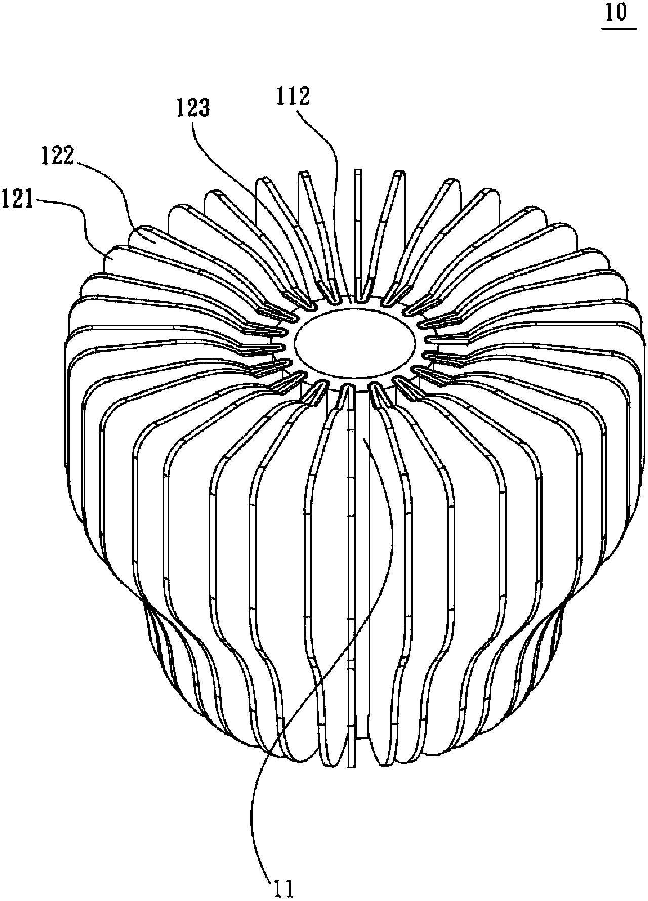
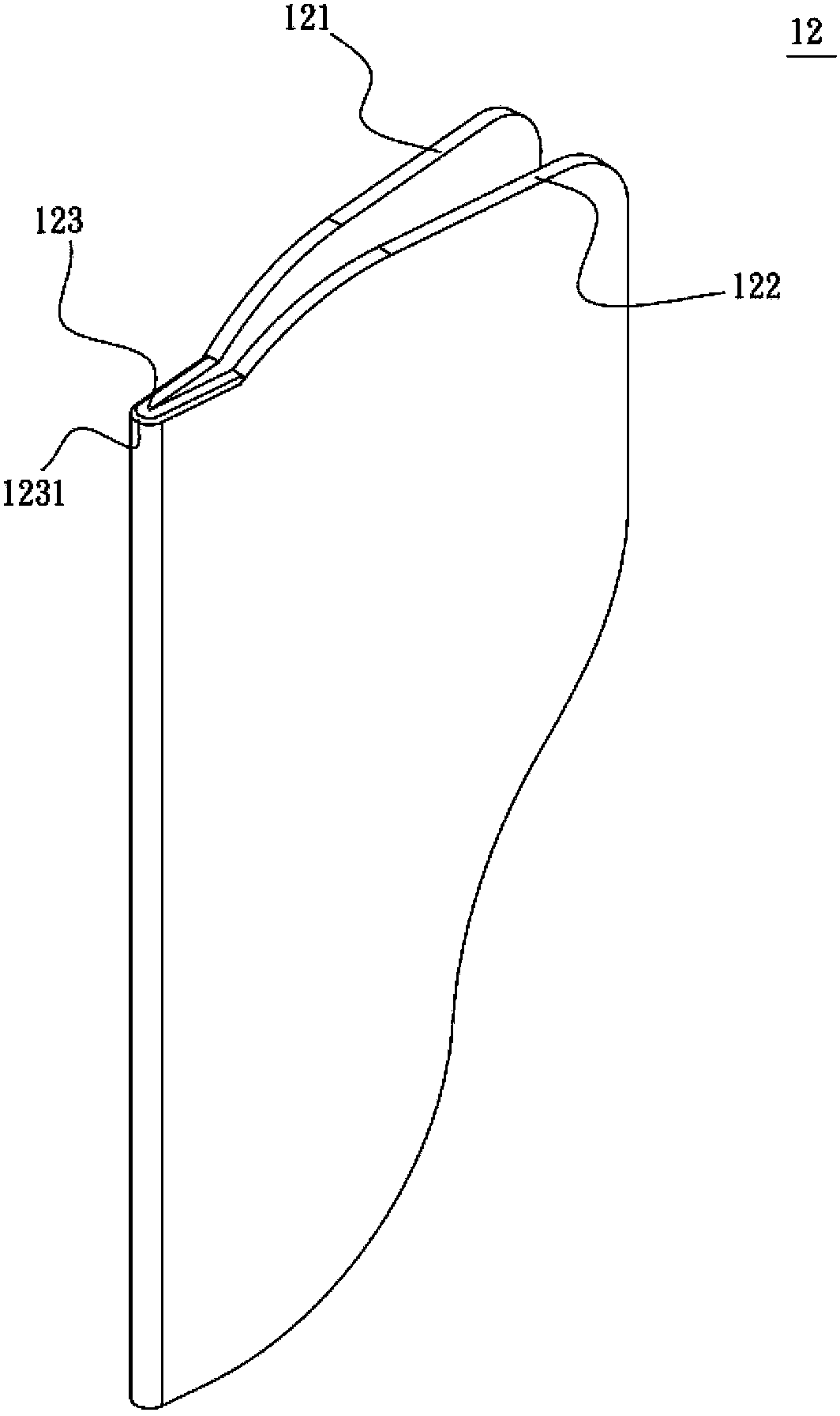
[0052] see figure 1 , figure 2 and image 3 , is a three-dimensional exploded schematic diagram, a three-dimensional combined schematic diagram and a schematic diagram of heat dissipation fins of the first preferred embodiment of the heat sink structure of the present invention. As shown in the figure, the heat sink 10 of the present invention includes a body 11 and a plurality of heat dissipation fins 12;

[0053] The body 11 has a first end 111 and a second end 112, a longitudinal direction a is defined between the first end 111 and the second end 112, and the body 11 has a A coupling channel 113 is distributed around the body 11 , the coupling channel 113 extends from the first end 111 along the longitudinal direction to the second end 112 and passes through the first end 111...


PUM


Abstract

Disclosed are a radiator structure and a production method thereof. A radiator comprises a body and a plurality of radiating fins. The body is provided with a first end and a second end with the lengthwise direction defined therebetween. The radiating fins are arranged in a forming die, the body is enabled to be pushed into the forming die at a high speed in a machining mode, and bending sections of the radiating fins in the forming die facing toward the body are forced into combined slots from the first end and move along the lengthwise direction to the second end to be combined on the surface of the body.

Description

technical field [0001] The invention relates to a radiator structure and its manufacturing method, especially to an annular radiator structure and its manufacturing method. Background technique [0002] The known cylindrical radiator includes a cylinder and a plurality of fins connected to the surrounding surface of the cylinder. The known technology discloses the connection method between the fins and the surrounding surface of the cylinder as follows: [0003] 1. The case of patent application No. 098105429 in Taiwan, China discloses a method for planting and tightening tubular radiator fins and its application device, which mainly includes: a motor driven by a power source to generate step-by-step rotation Die base; provide a cylinder, the cylinder is positioned on the mold base, and the surrounding surface of the cylinder is provided with many grooves; provide a fin group, including a plurality of fins, and the fin group is set on one end side of the mold base , when th...

Claims


Application Information

Patent Timeline
IPC IPC(8): F28F7/00B21D39/00B21D37/10
Inventor 林胜煌林国胜
Owner ASIA VITAL COMPONENTS SHENZHEN CO LTD
Why Eureka
Try Eureka