Micro loudspeaker box with telescopic resonance chamber

A technology of telescopic resonance cavity and micro-speaker, applied in transducer shell/cabinet/stand and other directions, can solve the problems of device being easily damaged, easy to fall into dust, sundries, etc., and achieve the effect of suppressing dust

Inactive Publication Date: 2014-02-12
刘骏涛
View PDF8 Cites 2 Cited by
  • Summary
  • Abstract
  • Description
  • Claims
  • Application Information

AI Technical Summary

Problems solved by technology

Since the sound outlet is located on the upper shell of the speaker, and most of them are located on the top, it is easy to fall into dust, sundries, etc., and the internal components of the miniature speaker such as the sound outlet, horn, and telescopic resonance chamber are easily damaged.

Method used


Image

  • Micro loudspeaker box with telescopic resonance chamber
  • Micro loudspeaker box with telescopic resonance chamber

Examples


Embodiment Construction

[0019] The present invention will be further described below in conjunction with the accompanying drawings and preferred embodiments.

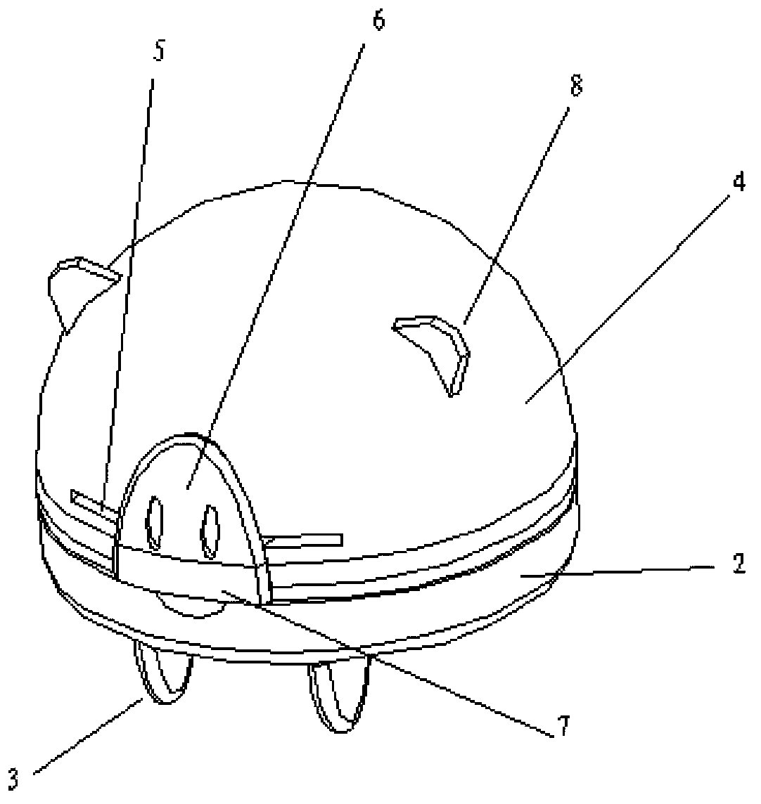
[0020] The miniature sound box with telescopic resonance chamber of the present invention comprises a speaker, a sound box upper case, a sound box lower case, an audio cable, an audio plug, a circuit board and a telescopic resonance chamber, the sound box upper case is fixedly connected with the sound box lower case, and the sound output The hole is located on the lower case of the sound box, the speaker is located in the lower case of the sound box, and the sound of the miniature sound box propagates downward from the speaker through the sound hole on the lower case of the sound box.

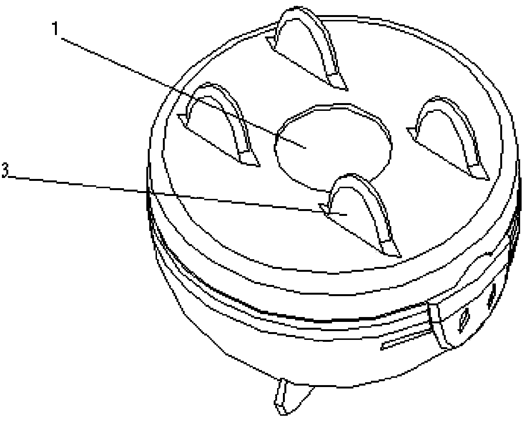
[0021] Such as figure 1 , figure 2 As shown, the sound box lower case 2 is circular, and the sound hole 1 of the miniature sound box is located at the bottom center of the sound box lower case 2, and the sound hole 1 is mostly circular, because the circle can...


PUM


Abstract

A miniature sound box provided with a telescopic resonance cavity comprises a loudspeaker, a sound box upper casing (4), a sound box lower casing (2), an audio cable, an audio plug, a circuit board, and a telescopic resonance cavity, the sound box upper casing (4) being fixedly connected to the sound box lower casing (2), and sound outlets (1) being provided on the sound box lower casing (2). A bottom portion of the sound box lower casing (2) is provided with multiple legs around the sound outlets (1) to support the miniature sound box, so that the sound from the miniature sound box is transmitted downwards from the loudspeaker through the sound outlets (1) on the sound box lower casing (2), thereby preventing dust and sundries from falling into the sound box, and reducing the damage to the sound box inner devices such as the sound outlets (1), the loudspeaker, and the telescopic resonance cavity.

Description

technical field [0001] The invention relates to the field of miniature sound boxes, in particular to a miniature sound box with a telescopic resonance cavity. Background technique [0002] I have applied for a micro-speaker patent in China, the patent application number is 201220386162.X, the micro-speaker includes a speaker, a speaker upper case, a speaker lower case, an audio cable, an audio plug, a circuit board and a telescopic resonance cavity. The upper shell of the speaker is fixedly connected with the lower shell of the speaker. The telescopic resonance cavity is located in the upper shell of the speaker and the lower shell of the speaker. The upper end of the telescopic resonance cavity is connected to the upper shell of the speaker through a transition piece, and the other end is connected to the lower shell of the speaker; And placed in the upper shell of the sound box, the speaker transmits sound outward through the sound hole on the upper shell of the sound box....

Claims


Application Information

Patent Timeline
Patent Type & Authority Applications(China)
IPC IPC(8): H04R1/02
CPCH04R1/02
Inventor 刘骏涛
Owner 刘骏涛
Why Eureka
Try Eureka