Pipe fitting and hose

A technology of pipe joints and shapes, applied in the field of hoses, which can solve the problems of the overall length of the pipe joint 100 becoming longer, the number of parts increasing, and the outer diameter of the pipe joint becoming larger, etc.

Inactive Publication Date: 2009-12-30
BRIDGESTONE CORP
View PDF2 Cites 15 Cited by
  • Summary
  • Abstract
  • Description
  • Claims
  • Application Information

AI Technical Summary

Problems solved by technology

[0009] In addition, in the separable pipe joint 100, the outer diameter of the pipe joint increases due to the annular cover 124, and the number of parts increases, which increases the cost.
In addition, there is an excess pushing amount of the convex body 102 in the concave body 110 for separation work, and there is also a disadvantage that the overall length of the pipe joint 100 becomes longer.

Method used


Image

  • Pipe fitting and hose
  • Pipe fitting and hose
  • Pipe fitting and hose

Examples


Embodiment Construction

[0075] Embodiments of the present invention will be described below with reference to the drawings.

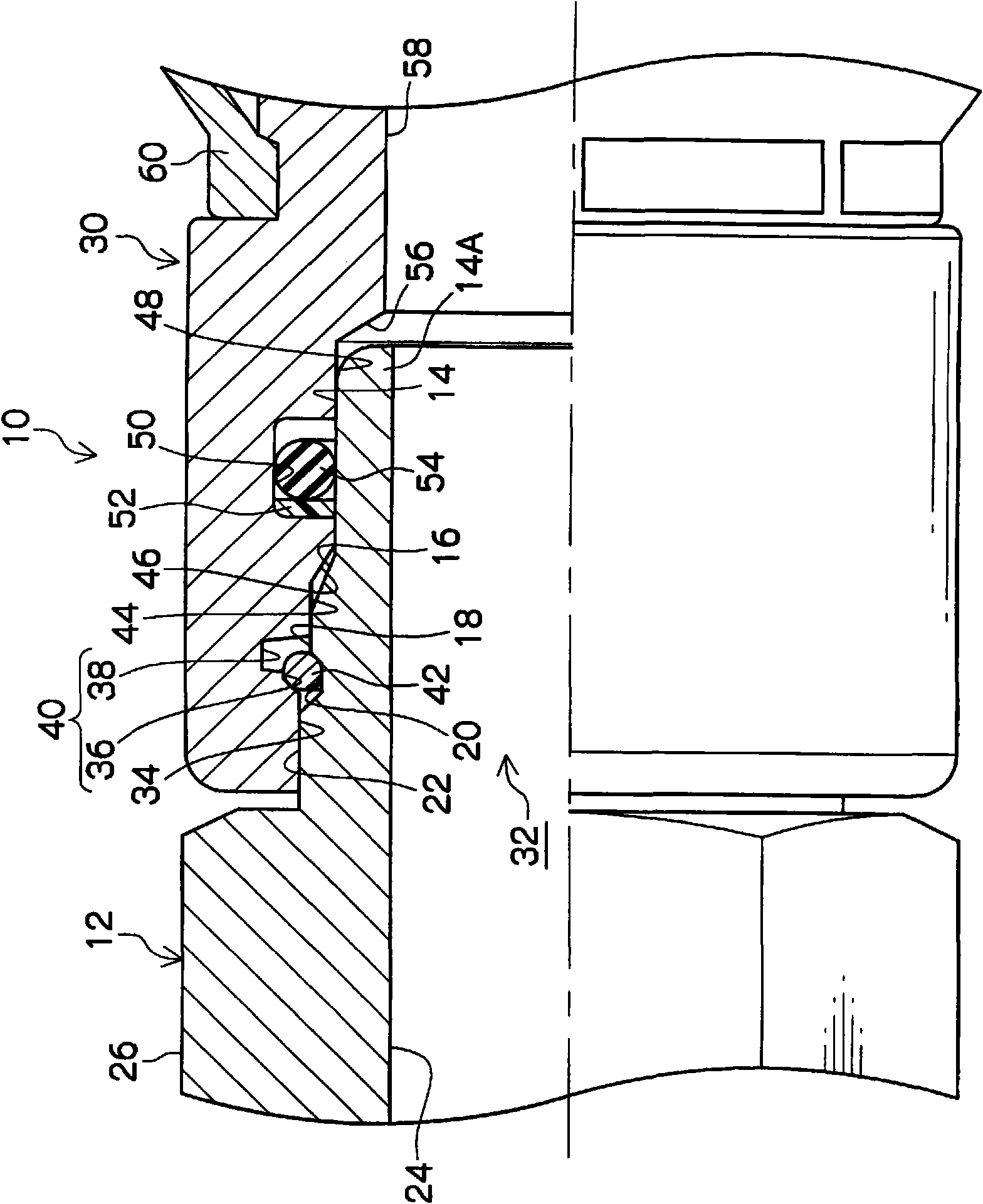
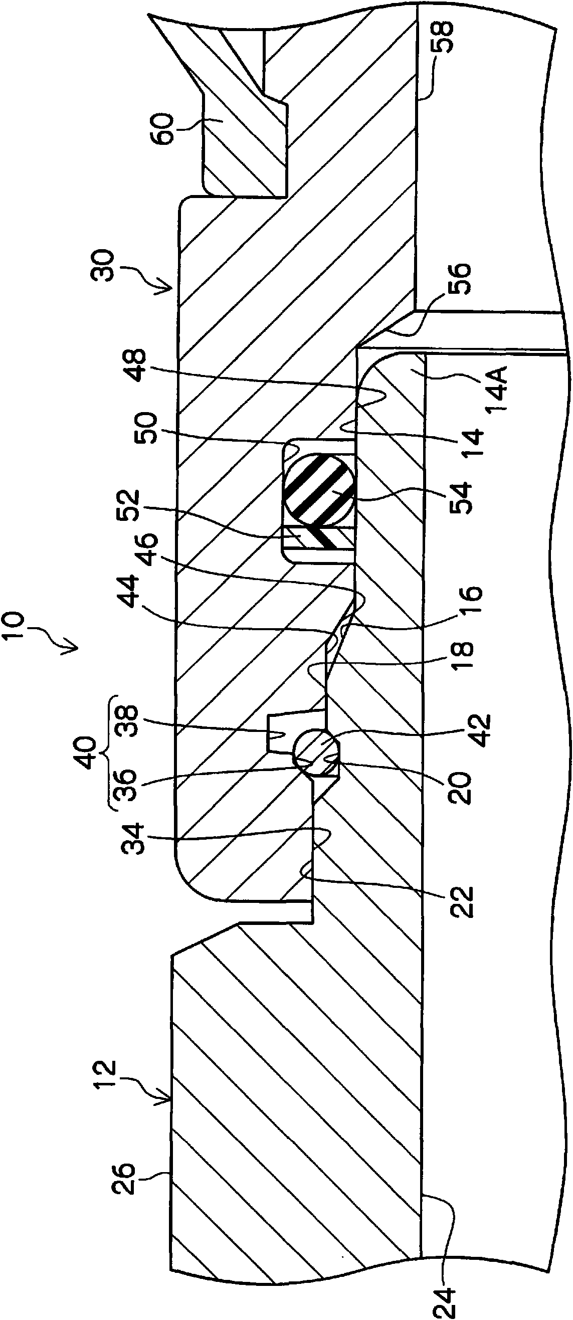
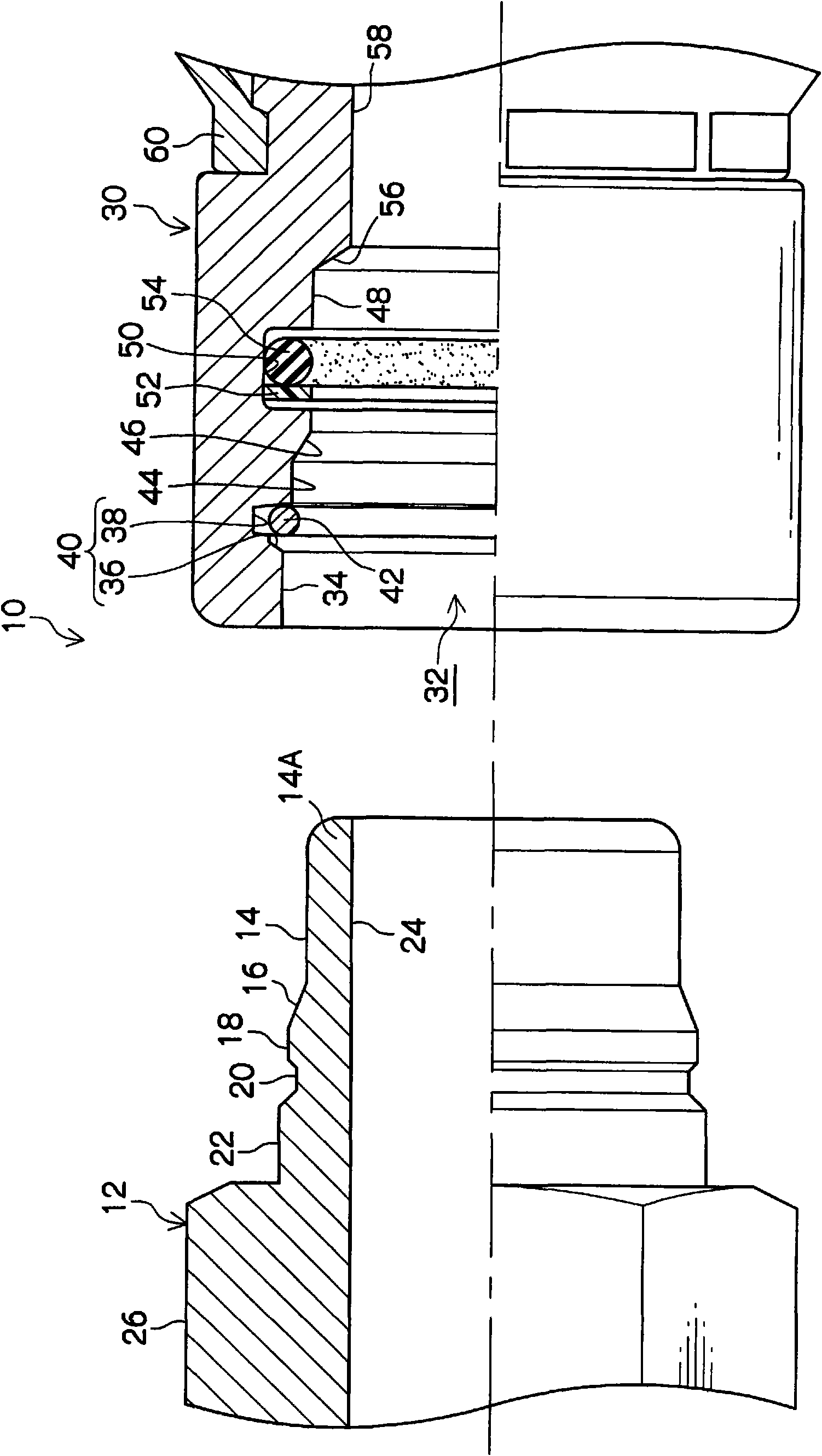
[0076] figure 1 It is a half-broken sectional view showing the coupling state of the pipe joint 10 according to the first embodiment of the present invention, figure 2 is a partially enlarged view of the pipe joint 10 . in addition, image 3 It is a half-broken sectional view showing the separated state of the pipe joint 10 .

[0077] The pipe joint 10 is composed of a cylindrical male body 12 and a cylindrical female body 30 into which the male body 12 is inserted. Such as figure 1 and image 3 As shown, the front end side in the length direction of the convex body 12 is a small diameter, and includes in sequence from the front end toward the root: a third cylindrical portion 14; The outer tapered portion 16 of the cylindrical portion 14 is inclined outward; and the second cylindrical portion 18 having an outer diameter larger than that of the third cylindrical porti...


PUM


Abstract

A small pipe fitting in which a male body and a female body cannot be separated after they are coupled once. The pipe fitting (10) consists of a male body (12), and a female body (30) into which the male body (12) is inserted. The male body (12) has a smaller outside diameter on the distal end side and includes, sequentially from the distal end, a third cylindrical portion (14), an outer tapered portion (16), a second cylindrical portion (18), an annular groove (20) locked with a resilient stop ring body (42), and a first cylindrical portion (22). The female body (30) has a smaller inside diameter on the rear side and includes, sequentially from the distal end and from the inlet side of an opening (32), a first inner wall face (34), a two-step groove (40) consisting of a locking groove (36) and a containing groove (38) and containing the resilient stop ring body (42), a second inner wall face (44), an inner tapered portion (46), and a third inner wall face (48). The resilient stop ring body (42) has a gap (43) formed by cutting a part of an annular member, wherein the outer circumferential diameter when the resilient stop ring body (42) is deformed resiliently to allow the end faces (42A, 42B) of the gap (43) to touch each other is set smaller than the inside diameter of the first inner wall face (34).

Description

technical field [0001] The present invention relates to a pipe joint having a cylindrical male body and a cylindrical female body into which the male body is inserted, and a male body having the pipe joint, which are used for connecting pipes of motor vehicles, construction machinery, and working machines, etc. and a hose of at least one of the concave bodies. Background technique [0002] Conventionally, when assembling one pipe and another pipe, a pipe joint was used for connection. [0003] For example, if Figure 27 As shown, the pipe joint 100 is composed of a cylindrical male body 102 and a cylindrical female body 110 having an opening 112 into which the male body 102 is inserted. An annular groove 104 for locking the elastic annular body 120 is formed on the peripheral surface of the convex body 102 . An annular groove 114 is formed on the inner side of the opening 112 of the concave body 110 , and an O-ring 116 is provided in the groove 114 . An annular small-diam...

Claims


Application Information

Patent Timeline
Patent Type & Authority Applications(China)
IPC IPC(8): F16L37/08
CPCF16L33/2073F16L37/0887
Inventor 有动史康三根研二中林邦明
Owner BRIDGESTONE CORP
Why Eureka
Try Eureka