
A method and device for switching

A post-handover and successful handover technology, applied in electrical components, wireless communication, etc., can solve problems such as interruption and increase of UE communication, and achieve the effect of reducing the risk of communication interruption

Active Publication Date: 2017-08-11
DATANG MOBILE COMM EQUIP CO LTD
View PDF5 Cites 0 Cited by
  • Summary
  • Abstract
  • Description
  • Claims
  • Application Information

AI Technical Summary

Problems solved by technology

[0009] A method and device for handover provided by the embodiments of the present invention are used to solve the problem that in the existing E-UTRAN network architecture in the prior art, since the handover frequency and times of the UE are greatly increased, the number of handovers of the UE is increased. risk of communication disruption when

Method used


Image

  • A method and device for switching
  • A method and device for switching
  • A method and device for switching

Examples


example 1

[0133] See Figure 13 The method for carrying out bearer separation and handover in this embodiment is applied to the UE located in the overlapping coverage area of ​​a macro cell (macrocell) and a target local cell (target local cell). The method includes the following steps:

[0134] Step 131: The macro cell judges whether the UE connected to it needs to perform bearer separation handover;

[0135] If yes, go to step 132;

[0136] If not, the process ends.

[0137] Preferably, the macro cell can determine whether the UE needs to perform bearer separation handover according to the measurement report of the UE, the location information of the UE or the service information of the UE.

[0138] Step 132: The macro cell sends a bearer separation command (for example, "RB handover message") to the UE, where the bearer separation command at least includes: the identifier of the target local cell and an indication for indicating that the UE needs to be separated from the bearer of the target l...

example 2

[0196] See Figure 16 The method for carrying out bearer aggregation handover in this embodiment is applied to a UE located in an overlapping coverage area of ​​a macrocell and a target local cell. The method includes the following steps:

[0197] Step 161: The macro cell judges whether the UE connected to it needs to perform bearer convergence handover;

[0198] If yes, go to step 162;

[0199] If not, the process ends.

[0200] Preferably, the macro cell can determine whether the UE needs to perform bearer aggregation switching according to the measurement report of the UE, the location information of the UE, or the service information of the UE.

[0201] Step 162: The macro cell sends a bearer convergence command (for example, "RB handover message") to the UE, where the bearer convergence command includes information for indicating the bearers that need to be converged to the macro cell, configuration information of the macro cell, and local cell information. Configuration informati...


PUM


Abstract

The embodiment of the invention relates to the technical field of wireless communication, in particular to a method and device for switching. The method and device for switching are used for solving the problem that according to an E-UTRAN structure in the prior art, due to the fact that the switching frequency and the switching times of UE are greatly increased, the risk of communication interruption is increased when the UE conducts switching. The method for bearer separation switching comprises the steps that after the UE receives a bearer separation order from a macro base station, an MAC layer entity and a PHY entity which correspond to a target base station of the UE after switching is conducted are established; bearers needing to be separated and delivered to the target base station are mapped to the MAC layer entity and the PHY entity which correspond to the target base station; connection of the bearers and the macro base station is kept and the bearers have the access to the target base station. The method achieves the function of bearer switching and further achieves the purpose of separation and convergence of the user plane bearer and the control panel bearer.

Description

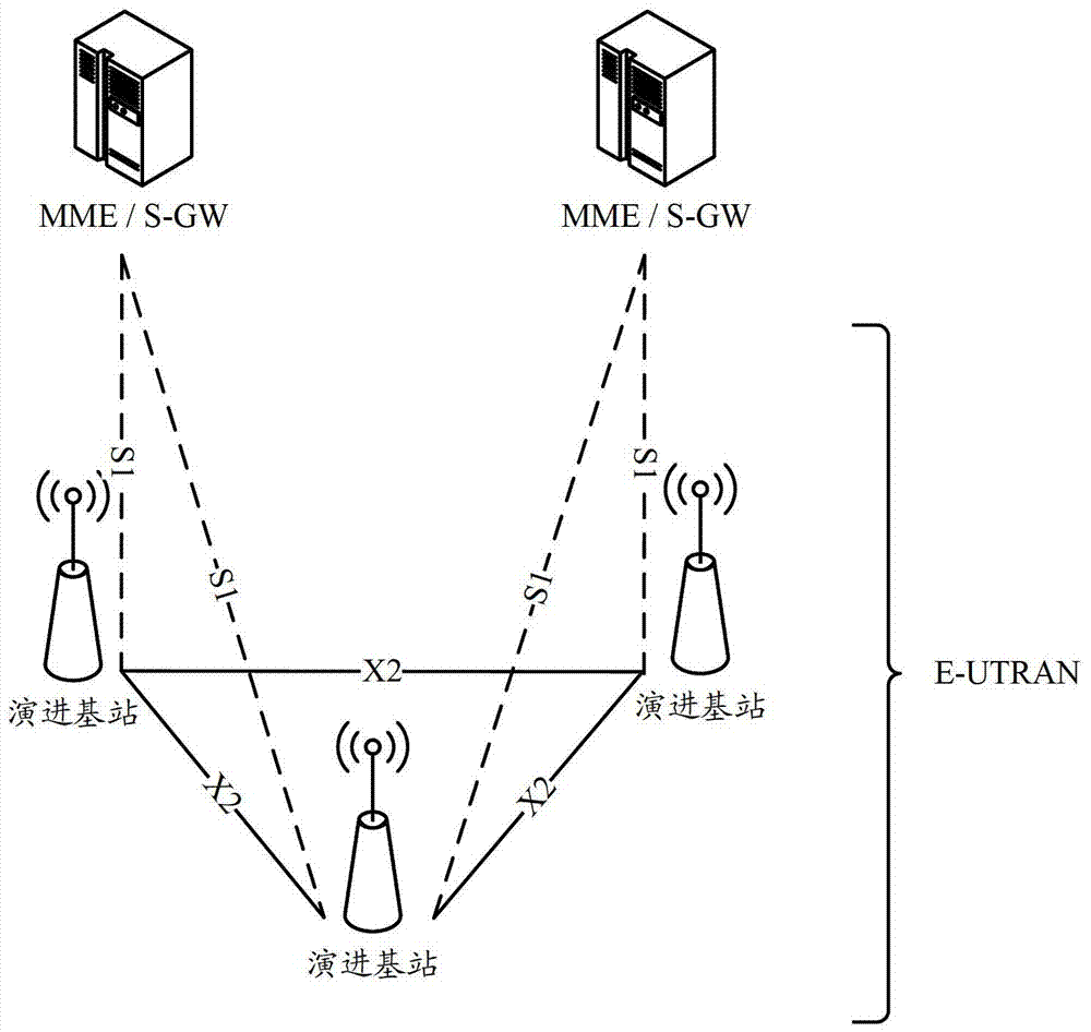
Technical field [0001] The present invention relates to the field of wireless communication technology, and in particular to a method and device for switching. Background technique [0002] Currently, the Evolved Universal Terrestrial Radio Access Network (E-UTRAN) is composed of eNBs (evolved base stations). For the network architecture of E-UTRAN, see figure 1 As shown, the mobility management entity (Mobility Management Entity, MME) is connected to the eNB through the S1-MME interface; the eNB completes the access network function and communicates with the user equipment (UE, User Equipment) through the air interface. For each UE attached to the network, there is an MME to provide services for it, and this MME is called the UE's serving MME. The S1-MME interface provides control plane services for the UE, including mobility management and data radio bearer (DRB) management functions; [0003] The Serving Gateway (S-GW) is connected to the eNB through the S1-U interface. For eac...

Claims


Application Information

Patent Timeline
Patent Type & Authority Patents(China)
IPC IPC(8): H04W36/08H04W36/18
Inventor 梁靖张大钧
Owner DATANG MOBILE COMM EQUIP CO LTD
Learn More