[0030] The present invention will be further described in detail below with reference to the accompanying drawings and specific embodiments.
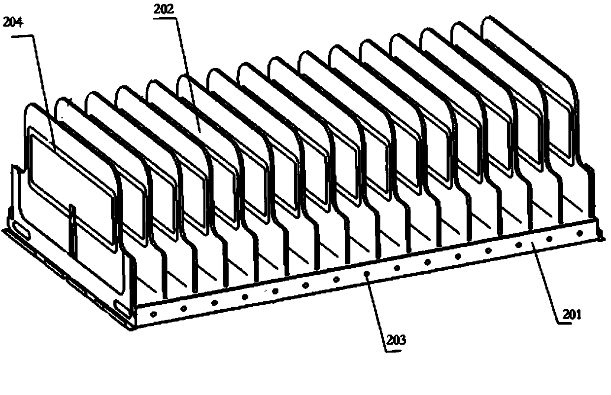
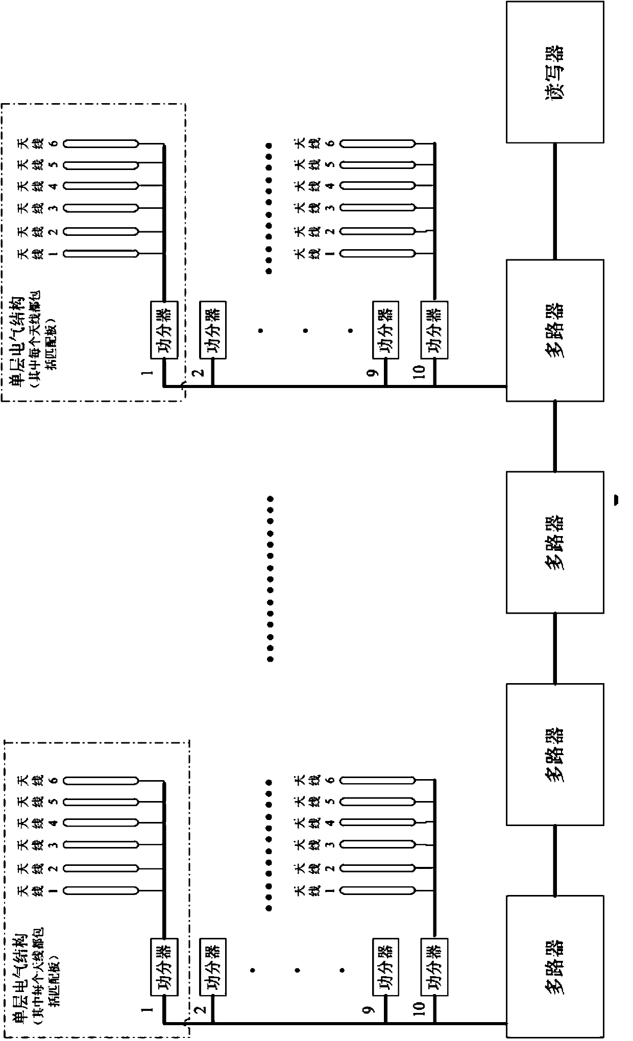
[0031] The intelligent filing cabinet provided by the present invention includes a cabinet body, several storage units inside the cabinet body, an electronic label, an RFID reading and writing module, a storage position indication module, a storage position sensing module and a main control system. The position sensing module and the RFID reading and writing module communicate with each other, and on the other hand, communicate with the computer on the workbench to realize the remote control of the intelligent filing cabinet by the computer.
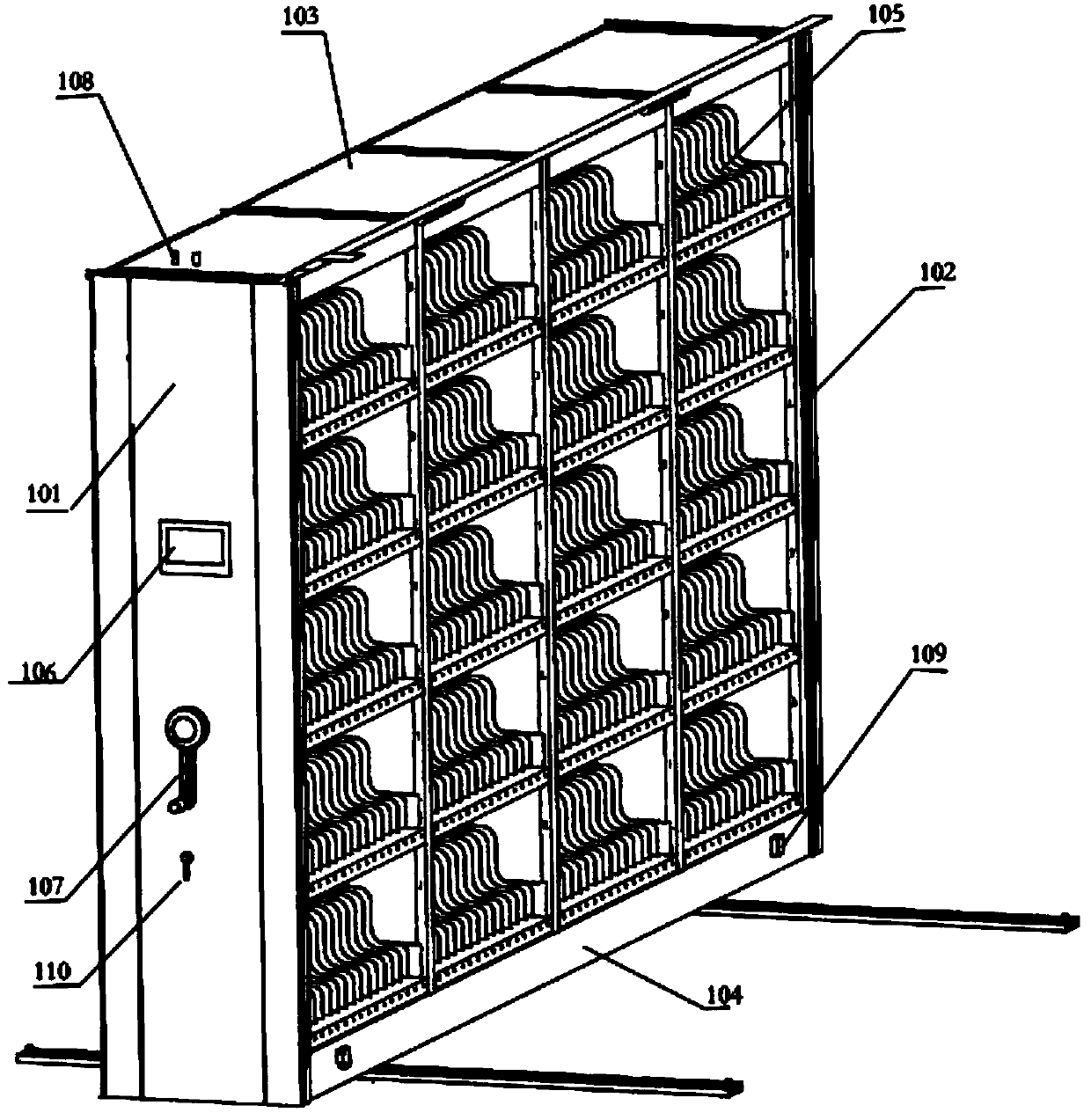
[0032] see figure 1 , the cabinet body includes a front panel 101 , a rear panel 102 , a cabinet door, a top panel 103 and a chassis 104 . The front panel 101, the rear panel 102 and the top panel 103 are all made of steel plates; the cabinet doors are located on both sides of the cabinet body and are made of glass. Inside the cabinet is an array composed of N*M (N, M are positive integers) storage units 105 . The front panel of the cabinet is equipped with a human-computer interaction module 106 . The human-computer interaction module 106 is preferably a touch screen, which is used to display the storage information of the filing cabinet, and at the same time, it is convenient for management personnel to monitor and operate the cabinet. In addition, temperature and humidity sensors and alarms are installed inside the cabinet.
[0033] figure 2 It is a schematic diagram of the structure of the storage unit 105 , including a tray 201 and a partition 202 . There are clapboard buckles on the tray to fix the clapboard. Each storage unit includes at least two partitions. The storage unit is double-column storage, and there are left and right file storage bins between the two partitions. The storage location indication module includes several indicator lights 203 for indicating the location of the file box or file volume. Each indicator light 203 corresponds to a file bin and is located at the bottom facing edge of the tray. The position sensing module is one of infrared non-contact sensors, spring-type microswitches, and pressure sensors, which are used to sense whether the file position is occupied. Wherein, the infrared non-contact sensor or the pressure sensor is arranged on the bottom tray corresponding to each file position; and the spring-type microswitch is placed in the file position.
[0034] combine figure 2 and image 3 , the RFID reading and writing module includes a reader, a multiplexer, a power divider and an antenna 204; the reader is connected to a plurality of multiplexers; the output of each multiplexer is connected to a plurality of power dividers; the power divider will The radio frequency signal is divided into the antenna 204 . The antenna 204 sends the radio frequency signal to the electronic tag in the form of electromagnetic waves; the electronic tag is activated after obtaining the energy carried by the radio frequency signal, and sends the electronic tag information to the reader through the antenna 204, the power divider, and the multiplexer.
[0035] The reader is the radio frequency transmitting part of the intelligent filing cabinet, which is located inside the top panel of the cabinet. The reader adopts multi-channel BNC (Bayonet Nut Connector, bayonet nut connector) connector output, and each channel of RF output corresponds to a channel of multiplexer. High frequency signals are used in the present invention. Compared with UHF signals, high frequency does not reflect, and its magnetic field is continuous, with clear boundaries, clear features, and strong distribution regularity. It is easy to control the detection range of the magnetic field through antenna technology, and there is no accidental reading or accidental missed reading. . In addition, the high frequency signal is not sensitive to the metal influence of the filing rack, and will not cause unstable detection performance due to metal reflection or detection of labels on other filing racks. The 18000-3MODE3 protocol is adopted in the radio frequency transmitting part, and the data communication is in the PJM (Phase Jitter Modulation) mode, which can effectively prevent the electronic tag from being detected due to the air attenuation of the radio frequency signal or the weak signal, so as to fully realize the Tag recognition at the single file level, and even tag recognition at the single page level. In addition, the 18000-3MODE3 protocol supports simultaneous detection of 8 channels, and the electronic tag can return information through any unblocked channel, which greatly improves the detection rate of the electronic tag. The communication rate between the 18000-3MODE3 protocol and the electronic label can reach 106kbit/s, and the mode of using 8 channels to work at the same time can achieve a maximum detection speed of 700 pieces/second.
[0036] The multiplexer is located inside the top panel of the cabinet and is used to switch and output multiple RF signals. The multiplexer can realize one radio frequency signal input and multiple radio frequency signal output, and the multiplexers can be cascaded, and used in conjunction with the multi-channel reader, which can improve the utilization rate of the reader. The reader/writer switches and controls the multiplexer in a time-sharing manner, so that the multiplexer only outputs one radio frequency signal to the power divider. The power divider is connected to a plurality of antennas 204 and is fixed inside the tray. The power divider combines two technologies of radio frequency time-sharing switching and power division: first, one radio frequency signal is divided into two radio frequency signals through the power division technology and output at the same time, and the two radio frequency signals are connected to two adjacent antennas for the purpose of Strengthen the magnetic field between the two antennas; secondly, the reader performs time-sharing switching by controlling the power divider, so that the two adjacent antennas have radio frequency signal output. The invention adopts the radio frequency switching technology that combines time division switching and power division switching, so that when one reader works, the energy carried by the radio frequency signal can be transmitted to the two antennas through the radio frequency signal, so that only two adjacent antennas are at the same time. Each antenna is in the detection state, which can effectively control the range and intensity of the electromagnetic wave of the antenna; through these two control methods, the radio frequency signal can be switched to different antenna groups, different layers and different racks, ensuring the success rate of electronic tag detection and effectively reducing reading and writing. The number of devices, saving equipment costs.
[0037] The antenna 204 is close to the partition and fixed in the groove of the tray. The antennas are in the form of an array with matching plates in each antenna 204 . Two adjacent antennas are grouped together. There are multiple partitions between the antennas, and the number of partitions needs to be selected according to the size of the actual storage space. The selection of the size, shape and working power of the antenna needs to be determined according to the number of tags read. Through time-division switching and power-division switching, only one set of antennas works at the same moment. Therefore, when fine-tuning the power of the antenna, after the two adjacent antennas are superimposed, the tags covered by them can obtain enough energy to be recognized, while other tags that are not within the recognition range cannot be detected if they do not obtain enough energy. . The improvement of the antenna not only ensures the reading success rate of a single antenna, but also effectively controls the recognition range of the antenna, thereby realizing page-level detection and identification.
[0038] In the present invention, the electronic label is pasted on the spine and the back of the file box in an "L" shape, or on the back of the file roll. The position of the electronic tag should be in the optimal detection area of the antenna, that is, the strongest position of the antenna energy. Since the waveform of the high-frequency antenna is a closed electromagnetic wave, the center energy of the electromagnetic wave is the strongest. After the antenna is installed, measure the intensity of the electromagnetic wave, and make the labeling position of the file bag and the file box at the strongest position of the antenna energy. In the present invention, the electronic label is assigned different application family identifiers according to the two categories of the file box and the file volume. The reader/writer distinguishes the file box and the file bag according to different application family identifiers. Only the electronic tag with the same application family identifier and the command sent by the reader will return, otherwise the electronic tag will not return information. Each electronic tag has its corresponding UID (User Identification, user identification). Before reading the stored data of all electronic tags, the reader first reads the UID numbers of all electronic tags, and then sends commands for a certain UID (that is, a certain electronic tag); only one electronic tag is reading and reading at the same time. Writers exchange data. According to the application family identifier and the UID number of the electronic label, the location of the file box and the file volume can be accurately determined.
[0039] Faced with the problem of overlapping electronic tags in file volume detection, the two main factors that affect the reading effect of overlapping electronic tags are energy reduction and frequency offset. Since the resonant frequency of the electronic tags will be reduced after overlapping, the present invention solves the problem of overlapping electronic tags from the following two aspects: adjusting the frequency of the electronic tags so that the resonant frequency is exactly at the high frequency adopted by the present invention when multiple electronic tags overlap. Frequency (13.56MHz); adjust the frequency of the reader, so that the RF transmission frequency of the reader is the same as the resonance frequency of the overlapping electronic tags, at this time, the overlapping tags can be read. When the frequency of the reader and the electronic tag is the same, the electronic tag can obtain more energy, so that it can be detected better. For non-overlapping tags, although the resonant frequency of the electronic tags is slightly different, the energy consumption for reading non-overlapping tags is small, and the reader can still read the electronic tags accurately at this time.
[0040] In a preferred embodiment of the present invention, the cabinet structure is a 1*5 storage unit array, that is, the cabinet includes a 5-layer structure, and each layer has one storage unit. Each storage unit includes 16 partitions and 6 antennas 204 . Every two antennas is a group, that is, the two antennas 1 and 2 are the first group, the two antennas 2 and 3 are the second group, the two antennas 3 and 4 are the third group, and the two antennas 4 and 5 are the first group. Four groups, 5 and 6 antennas are the fifth group. The 6 antennas of each storage unit share a power divider. One multiplexer controls 10 power dividers, that is, one multiplexer controls 2 intelligent filing cabinets. The reader is preferably a long-distance four-channel reader with 4 RF outputs, that is, 8 smart filing cabinets can share one reader, and can poll up to 4*10 antennas. Of course, the number of antennas, power dividers, multiplexers and readers can also be adjusted according to the actual situation.
[0041] The main control module is the control center of the cabinet, which is used to receive the instructions of the workbench to complete the reading of the electronic label. At the same time, it also collects and processes various information inside the cabinet and displays it by the human-computer interaction module. The main control module can be implemented by programmable logic devices such as FPGA or CPLD. When the file manager needs to find a file, the computer of the workstation enters the file name, and searches for the UID number of its electronic label according to the corresponding name. According to the searched electronic tag UID number, the main control system sends corresponding instructions to the reader. The reader polls all antennas on command. When the file box to be found is detected, the reader will return the specific location of the file (section, shelf, layer) to the workbench, and the indicator light of the warehouse will be on at the same time, thereby intelligently guiding the administrator to complete the search work.
[0042] There are two ways to store the file box, the designated location and the non-designated location. First, the storage of the file boxes at the specified location is introduced: the workbench specifies the location where the file boxes are placed, sorts the placed locations, and sends the data to the control system of the file cabinet; the main control system automatically opens the cabinet according to the data, And light the indicator light at the designated position of the system; the file management personnel put it into the file box according to the guidance of the indicator light; the position sensing module senses the signal, controls the RFID read-write module to read the electronic label of the file box and the file volume, and returns the data Workbench to judge whether the file box is placed correctly; if the placement is incorrect, the main control system will give a dislocation prompt. Secondly, the storage of file boxes without a specified position is introduced: the main control system automatically opens the cabinet, and the file management personnel put a file box at will; the main control system records the storage position of the file box according to the storage position sensing module, and controls the RFID read-write module to read at the same time. File box and file volume information, and return the obtained position information and electronic label information to the workbench. The file management personnel put in the next file box in turn, until all file boxes are put on the shelf and put into storage.
[0043] The intelligent filing cabinet is also provided with a mobile control module, including an electric control system, a transmission device, a manual crank 107, an infrared anti-squeeze sensor 108, a metal sensor 109, a column lock 110 and a lighting device. Cabinet movement can be controlled by manual, human-computer interaction modules, and remote workbenches. The mobile control module communicates with the main control module of the cabinet, and the manual crank 107 is connected to the transmission device. The electronic control system is respectively connected with the transmission device, the infrared anti-extrusion sensor 108 , the metal sensor 109 and the lighting device. The manual crank handle 107 is located on the front panel of the cabinet body; the transmission device controls the movement of the cabinet body and the opening and closing of the cabinet door, and is located on the guide rail. The infrared anti-squeeze sensors 108 are respectively installed on the left and right sides of the lower edge of the cabinet door. When there is an object between the two sensors, the cabinet stops moving. The metal sensor 109 is located on the top of the cabinet, and each cabinet is equipped with two metal sensors. The first metal sensor 109 of the cabinet body decelerates and moves after sensing the adjacent cabinet body; the second metal sensor 109 stops moving after sensing the adjacent cabinet body. The column lock 110 is located on the lower part of the front panel of the cabinet. When there are multiple smart filing cabinets, the tops are connected by a V-shaped connection frame, and the bottoms are located on the same guide rail, so that the mobile control module can control the movement of the cabinet.
[0044] The following introduces the intelligent file management system based on the above-mentioned intelligent filing cabinet. The intelligent file management system includes at least two intelligent filing cabinets, workbenches, RFID access control, RFID printers and personnel work permits. The intelligent filing cabinet includes a master control column and at least one slave control column. The master control column communicates with its adjacent slave control column and workbench respectively. The adjacent slave control columns communicate with each other in pairs. In addition to controlling the file cabinets in this row, the master row also controls other slave rows in the cabinet group. The slave row only controls the file cabinet in this row. The workbench conducts data communication with smart filing cabinets, RFID security gates, RFID printers and personnel work cards respectively. The workbench includes a computer and an RFID input device, which is used for intelligent management such as real-time inventory, positioning and query of cabinet files. The RFID security gate is installed at the entrance of the archives to prevent abnormally borrowed files from being taken out of the archives. Personnel work permits provide corresponding permissions for personnel entering the archives. The RFID label printer initializes or enters the file information, and associates the file information with the radio frequency information and prints it on the electronic label.
[0045] The invention can read the label information on the file box and the file volume in the box in real time, and obtain the storage information of the file box or the file volume and the related information of the file, including file type, file quantity, level, box position, etc.; When the entered location does not match the relevant information recorded by the radio frequency tag, the administrator will be given a dislocation prompt. In addition, the intelligent filing cabinet can also monitor the in-position status of the filing box in real time, effectively reducing the inventory time of the administrator. In addition, parallel movement control operations can be performed on racks with more than thousands of columns, and physical and logical partitions can be performed according to the structure of the archives. For the real-time inventory of archive boxes and/or archive volumes, the inventory recognition rate can reach 100%, and for archive rooms with an archive box size of 20,000, the inventory time does not exceed 8 minutes.
[0046] The intelligent filing cabinet, the file management system and the file positioning method provided by the present invention have been described in detail above, but are not intended to limit the present invention. For those of ordinary skill in the art, any obvious changes made to the invention without departing from the essential spirit of the invention will constitute an infringement of the patent right of the invention and will bear corresponding legal responsibilities.