Antenna switchover method and terminal

An antenna switching and antenna technology, applied in antennas, wireless communications, electrical components, etc., can solve problems affecting the normal use of antennas

Active Publication Date: 2014-02-19
HUIZHOU TCL MOBILE COMM CO LTD
View PDF4 Cites 29 Cited by
  • Summary
  • Abstract
  • Description
  • Claims
  • Application Information

AI Technical Summary

Problems solved by technology

Moreover, when measuring the strength of the signal, it is necessary to switch to each antenn

Method used


Image

  • Antenna switchover method and terminal
  • Antenna switchover method and terminal
  • Antenna switchover method and terminal

Examples


Embodiment Construction

[0022] In the following description, for purposes of illustration rather than limitation, specific details, such as specific system architectures, interfaces, and techniques, are set forth in order to provide a thorough understanding of the present application. It will be apparent, however, to one skilled in the art that the present application may be practiced in other embodiments without these specific details. In other instances, detailed descriptions of well-known devices, circuits, and methods are omitted so as not to obscure the description of the present application with unnecessary detail.

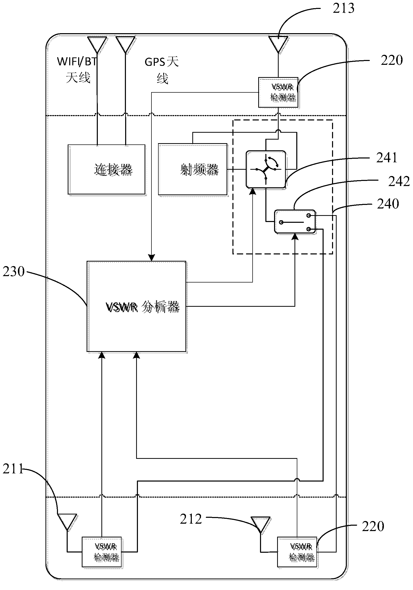
[0023] refer to figure 2 , figure 2 It is a structural schematic diagram of an embodiment of the terminal of the present invention. The terminal in this embodiment includes: a first main antenna 211, a second main antenna 212, an auxiliary antenna 213, a voltage standing wave ratio (Voltage Standing Wave Ratio, VSWR) detector 220, a voltage standing wave ratio analyzer 230, and...


PUM


Abstract

The invention discloses an antenna switchover method and a terminal. The terminal comprises a plurality of antennas, a voltage standing wave ratio detector, a voltage standing wave ratio analyzer and a switchover device, wherein the antennas comprise at least one main antenna and are connected with the voltage standing wave ratio detector, the voltage standing wave ratio detector is connected with the voltage standing wave ratio analyzer, and the voltage standing wave ratio analyzer is connected with the switchover device. The antenna switchover method comprises the steps that the voltage standing wave ratio detector detects the voltage standing wave ratio state of each antenna, the voltage standing wave ratio analyzer judges the performance of each antenna according to the voltage standing wave ratio state of each antenna to find out the antenna with the best performance, and the switchover device switches a work antenna to the antenna with the best performance, and data transmission is carried out by utilizing the antenna with the best performance.

Description

technical field [0001] The present application relates to the communication field, and in particular to an antenna switching method and a terminal. Background technique [0002] In order to obtain a better appearance design and save wiring area, more and more terminals use metal frames as multiple antennas and ground wires. refer to figure 1 , usually the slot between the antenna and the ground wire is set at the first position 110 on the upper part of the terminal or the second position 120 on the lower part of the terminal. [0003] Therefore, when the human hand is holding the terminal, the palm or fingers are easy to accidentally press the separation groove between the antenna and the ground wire, and people are conductors, so when the palm or fingers press the separation groove between the antenna and the ground wire When it is on, it is equivalent to connecting the antenna and the ground wire through the conductor, which greatly affects the performance of the antenna...

Claims


Application Information

Patent Timeline
IPC IPC(8): H04W88/02H04B1/40H01Q23/00H04B1/38
Inventor 陈志
Owner HUIZHOU TCL MOBILE COMM CO LTD
Why Eureka
Try Eureka