Imaging device and method

An imaging device and imaging parameter technology, applied in installation, optics, instruments, etc., can solve problems such as poor user experience, inconvenient use, and inability to converge

Active Publication Date: 2014-02-26
BEIJING ZHIGU RUI TUO TECH
View PDF14 Cites 11 Cited by
  • Summary
  • Abstract
  • Description
  • Claims
  • Application Information

AI Technical Summary

Problems solved by technology

[0003] However, in daily life, for users with hyperopia and normal diopters, it is generally difficult to see objects at very close distances; Both can see very close objects (such as mobile phone screens) clearly, but they cannot converge the images of the left and right eyes; and when wearing corrective glasses, they cannot see very close objects clearly (such as the Japanese patent with the publication number JP2007219462A (As shown in Figure 2-3 in the application)
Although, there are adjustable lenses by changing their own focal length and other imaging parameters (such as adjusting the diopter of the lens to 0 or even a positive number for myopia, and adjusting the diopter of the lens to a larger positive number than when looking farther away for hyperopia) , can solve the problem of seeing very close objects clearly, but because the convergence angle of the two eyes is too large to converge, the user can only use one eye to watch in this case, which seriously affects the user experience
[0004] Although the above-mentioned Japanese patent application with the publication number JP2007219462A records that a prism device is provided on the ordinary refractive correction glasses to help the convergence of the sight lines of the two eyes (see the examples shown in Figures 2-4 of the patent application), but It is very inconvenient to use and the user experience is not good

Method used


Image

  • Imaging device and method
  • Imaging device and method
  • Imaging device and method

Examples


Embodiment Construction

[0099] The method and device of the present invention are described in detail below with reference to the accompanying drawings and embodiments.

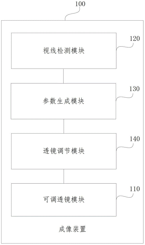
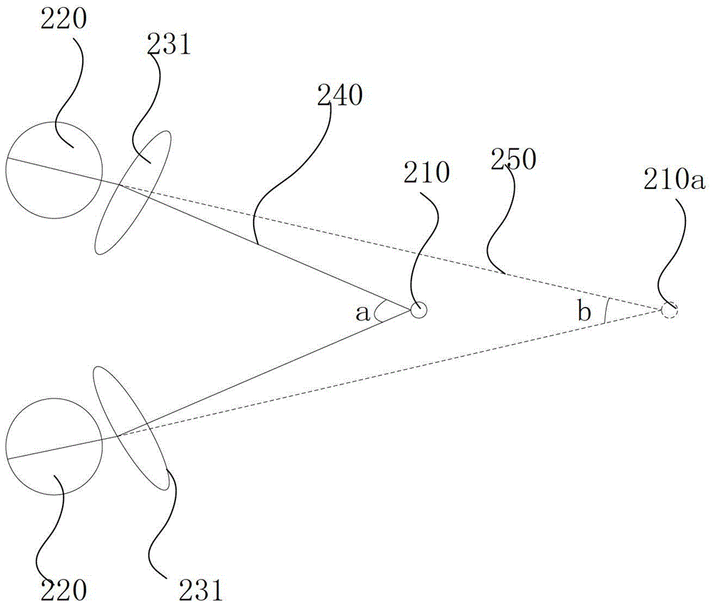
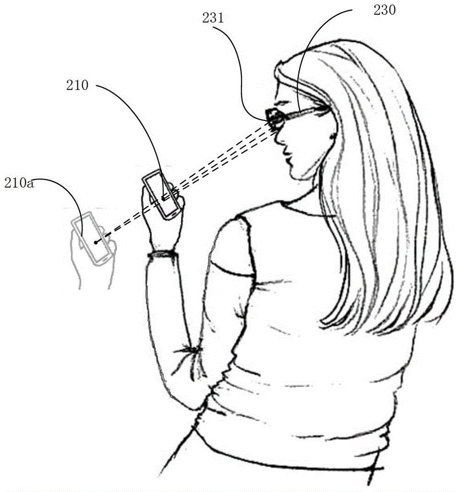
[0100] The resolution of the human eye is higher when the same object is located near than when it is located far away. Therefore, when the size of the display device is limited (such as a mobile phone) and more and richer content needs to be displayed, the If the display surface of the display device is arranged closer to the user's eyes, the resolution of the displayed content can be increased and richer content can be added. However, when the human eye looks at a very close object, on the one hand, the eye muscles need to be tensed, so that the pupil moves closer to the inner side of the eye, which makes the eyes easy to fatigue; Converge to the very close objects. Therefore, if figure 1 As shown, the embodiment of the present invention provides an imaging device 100, including:

[0101] The adjustable lens module 110 is used ...


PUM


Abstract

The invention discloses an imaging device and an imaging method. The device comprises an adjustable lens module used for imaging of an object of observation of eyes; a sight line detection module used for detecting a convergence parameter of the eyes at present; a parameter generation module used for generating an imaging parameter of the adjustable lens module based on the convergence parameter, the imaging parameter including an optical axis direction parameter; and a lens adjustment module used for adjusting the adjustable lens module based on the imaging parameter. The device and the method of an embodiment of the invention changes an actual convergence point of sight lines of the eyes by automatically detecting the convergence parameter of the eyes and adjusting the optical axis direction of the adjustable lens module between the eyes and the object based on the convergence parameter, thereby enabling a user to see an object nearby clearly in a relatively comfortable manner.

Description

technical field [0001] The invention relates to the field of imaging technology, in particular to an imaging device and an imaging method. Background technique [0002] The screen size and portability of mobile devices have always been a pair of insoluble contradictions. Although the screen resolution can be very high, due to the limitation of the screen size, it is impossible to display a lot of information under normal circumstances. If the user can use the mobile device at a closer distance, richer information can be displayed. [0003] However, in daily life, for users with hyperopia and normal diopters, it is generally difficult to see objects at very close distances; Both can see very close objects (such as mobile phone screens) clearly, but they cannot converge the images of the left and right eyes; and when wearing corrective glasses, they cannot see very close objects clearly (such as the Japanese patent with the publication number JP2007219462A as shown in Figure...

Claims


Application Information

Patent Timeline
Patent Type & Authority Applications(China)
IPC IPC(8): G02B7/34
Inventor 杜琳张宏江
Owner BEIJING ZHIGU RUI TUO TECH
Why Eureka
Try Eureka