Swinging driving device taking magnet and hall sensor as detection elements

A hall sensor, swing drive technology, applied in electrical components, electromechanical devices, electric components, etc., can solve the problem of not being able to accurately detect the absolute position of the swing swing, not detecting the swing swing, etc.

Inactive Publication Date: 2014-02-26
朱萱
View PDF8 Cites 10 Cited by
  • Summary
  • Abstract
  • Description
  • Claims
  • Application Information

AI Technical Summary

Problems solved by technology

[0002] Existing drive schemes for electric swings, cradles, cradles and rocking chairs (hereinafter referred to as swings) can only detect the approximate position of the swing, or detect the speed of the swing and the relative position of the swing, or detect the swing of the swing Direction, or not detecting the swing of the swing, neither can accurately detect the absolute position of the swing

Method used


Image

  • Swinging driving device taking magnet and hall sensor as detection elements
  • Swinging driving device taking magnet and hall sensor as detection elements
  • Swinging driving device taking magnet and hall sensor as detection elements

Examples


Embodiment Construction

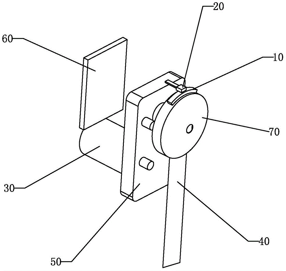
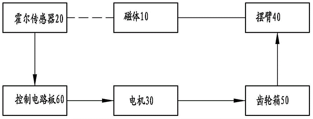
[0024] Such as figure 1 , image 3 Shown is the swing drive device of the present invention using magnets and Hall sensors as detection elements, applied to an electric swing device, including:

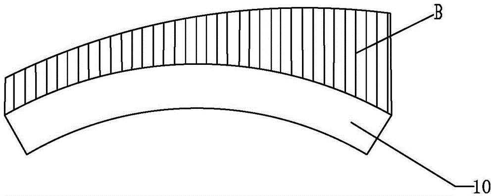
[0025] A magnet 10 fixed on an electric swing device. The magnetic field strength of the magnet 10 gradually weakens or increases from one end of the magnet 10 to the other end, see figure 2 ;

[0026] A Hall sensor 20 for detecting the magnetic field strength of the magnet 10 and inducing a voltage corresponding to the magnetic field strength B;

[0027] A motor 30 for driving the swing arm 40 of the electric swing device to swing;

[0028] A gear box 50, the input shaft of the gear box 50 is fixedly connected with the output shaft of the motor 30, and the output shaft of the gear box 50 is perpendicular and fixedly connected with the swing arm 40 of the electric swing device;

[0029] A control circuit board 60, the output end of the control circuit board 60 is connected to the motor 30, the...


PUM


Abstract

The invention discloses a swinging driving device taking a magnet and a hall sensor as detection elements. The magnet is fixed on a swinging arm of the swinging device such as a swing, the Hall sensor is fixed on a driving motor case of the swing, and a surface of the Hall sensor is close to a surface of the magnet; when the swing swings, the Hall sensor is close to different positions of the surface of the magnet when the swing swings to different angles, different voltages are induced by the Hall sensor, and the voltages represent the positions of the swing. A swinging direction and a swinging peak point of the swing can be calculated by utilizing the absolute position of the swing, an output voltage or a push period of a driving motor can be adjusted by a driving controller of the swing according to the swinging direction or the swinging peak point, and flexible swinging adjustment of the swing can be realized to adapt to use requirements of different users.

Description

Technical field [0001] The invention relates to an electric swing device, a swing drive device using magnets and Hall sensors as detection elements. Background technique [0002] Existing driver solutions for electric swings, cradles, cradles and rocking chairs (hereinafter referred to as swings) can only detect the approximate position of the swing, or detect the relative position of the speed and swing of the swing, or detect the swing of the swing Neither direction nor detection of the swing of the swing can accurately detect the absolute position of the swing. Summary of the invention [0003] In order to solve the above technical problems, the technical problem to be solved by the present invention is to provide a swing driving device that uses a magnet and a Hall sensor as detection elements. [0004] The technical scheme adopted by the present invention is: [0005] A swing drive device using magnets and Hall sensors as detection elements, applied to an electric swing device,...

Claims


Application Information

Patent Timeline
Patent Type & Authority Applications(China)
IPC IPC(8): H02K7/116
Inventor 朱萱
Owner 朱萱
Why Eureka
Try Eureka