
Configuration method and device of device to be monitored and monitoring system

A technology of monitoring equipment and monitoring system, which is applied in transmission system, digital transmission system, data exchange through path configuration, etc. It can solve the problems that affect the working efficiency of the monitoring system and the I/O points of the equipment to be monitored are easy to be confused.

Active Publication Date: 2014-02-26
FUJIAN LONGKING
View PDF4 Cites 6 Cited by
  • Summary
  • Abstract
  • Description
  • Claims
  • Application Information

AI Technical Summary

Problems solved by technology

[0004] At present, there are many devices to be monitored in the configuration monitoring system, and the number of I / O points of each device to be monitored is also large, so every time a monitoring system is established, a large number of I / O points need to be manually configured , which seriously affects the work efficiency of building a monitoring system, and when there are many devices to be monitored, it is easy to confuse the I / O points of different devices to be monitored

Method used


Image

  • Configuration method and device of device to be monitored and monitoring system
  • Configuration method and device of device to be monitored and monitoring system
  • Configuration method and device of device to be monitored and monitoring system

Examples


Embodiment Construction

[0048] The following will clearly and completely describe the technical solutions in the embodiments of the present invention with reference to the accompanying drawings in the embodiments of the present invention. Obviously, the described embodiments are only some, not all, embodiments of the present invention. Based on the embodiments of the present invention, all other embodiments obtained by persons of ordinary skill in the art without making creative efforts belong to the protection scope of the present invention.

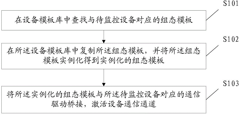
[0049] The invention provides a configuration method of equipment to be monitored, which is applied to the monitoring server of the configuration monitoring system, such as figure 1 As shown, the method includes the following steps:

[0050] Step S101: Search for the configuration template corresponding to the device to be monitored in the device template library. The configuration template corresponding to the device to be monitored is pre-stored in the devic...


PUM


Abstract

The invention provides a configuration method and device of a device to be monitored, and a monitoring system. A plurality of configuration templates are stored in a device template base of a monitoring server in advance. The configuration templates include the configuration template of the device to be monitored. Each configuration template comprises configuration information of I / O points of the device to be monitored, configuration information of monitored images, configuration information of alarm settings, and configuration information of tendency curves. The configuration templates complete configuration work of the device to be monitored in advance. When the configuration work is practically conducted, only the configuration template corresponding to the device to be monitored needs to be connected with a corresponding communication driver in a bridging mode, and the aim of configuring the device to be monitored into the monitoring server can be achieved when communication channels of the device are activated. In the configuration method and device of the device to be monitored, and the monitoring system, configuration is conducted through the configuration templates, and therefore the configuration process of the device to be monitored is greatly simplified, and not only can configuration be rapidly conducted, but also the problem that I / O points of different devices to be monitored are easily confused in traditional configuration can be solved.

Description

technical field [0001] The invention relates to the field of industrial monitoring, in particular to a configuration method, device and monitoring system of equipment to be monitored. Background technique [0002] In order to monitor a wide variety of control equipment with different standards and a large number of sets in industrial automation, a configuration monitoring system emerges as the times require. The currently widely used configuration monitoring system includes a monitoring server and devices to be monitored connected to the monitoring server. The main function of the monitoring server in the configuration monitoring system is to obtain and control the I / O parameters of the I / O points of the devices to be monitored. [0003] In order to achieve the purpose of monitoring, it is necessary to manually configure the I / O points of the equipment to be monitored one by one. Take an I / O point as an example, store the I / O point in the monitoring server with a unique name...

Claims


Application Information

Patent Timeline
IPC IPC(8): H04L12/26H04L29/08H04L29/06H04L12/46
Inventor 吴善荣钟至光肖华生李冬春
Owner FUJIAN LONGKING
Learn More