
Element-based covering system

A technology for covering elements and covering surfaces, applied in the direction of covering/lining, building components, floors, etc., can solve the problems of slow and difficult installation and disassembly, and achieve the effect of easy disassembly or change, rapid disassembly or change

Inactive Publication Date: 2014-02-26
亚尔莫·波隆宁
View PDF6 Cites 2 Cited by
  • Summary
  • Abstract
  • Description
  • Claims
  • Application Information

AI Technical Summary

Problems solved by technology

[0003] The known covering systems have the disadvantage that they are slow and difficult to install and remove

Method used


Image

  • Element-based covering system
  • Element-based covering system
  • Element-based covering system

Examples


Embodiment Construction

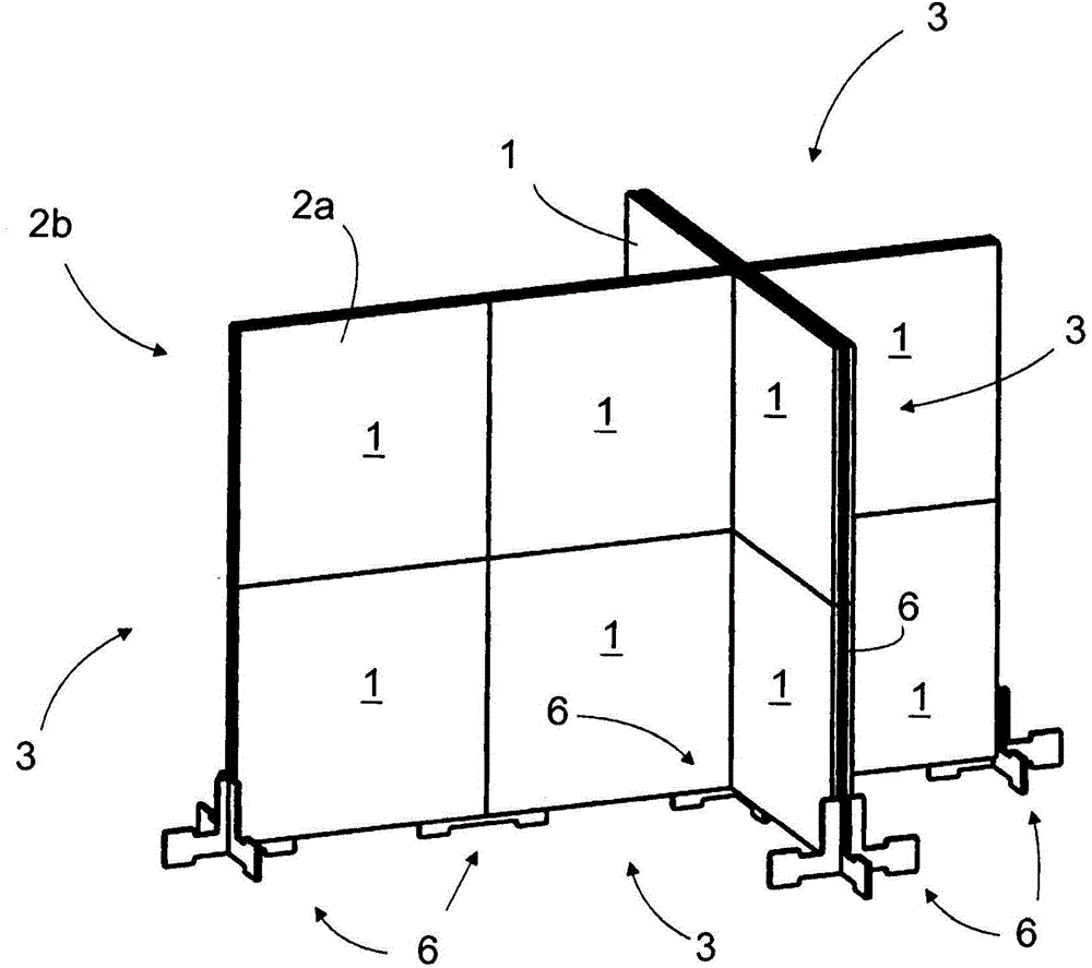
[0025] figure 1 is a schematic perspective view of a divider provided by the covering system of the present invention.

[0026] The partitions form partition walls arranged in a cross shape when viewed from the top. Obviously, the covering system also allows forming partitions of other shapes, the size of which can be freely selected from multiples of the covering system size.

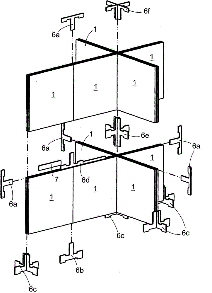
[0027] The partition comprises rectangular, more precisely square, covering elements 1 which are arranged side by side and one above the other.

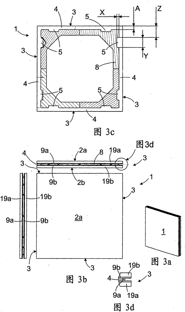
[0028] The covering element 1 comprises on its first side a first covering surface 2a and correspondingly on its second side a second covering surface 2b. The quality, material and other properties of the covering surfaces 2a, 2b may be such that they provide a finished surface visible eg in a room. Alternatively, a top element, such as a ceiling, constituting a surface visible in the room is attached to the covering surfaces 2a, 2b. It should be noted th...


PUM


Abstract

A covering system comprising a rectangular covering element (1) having a first covering surface (2a) and a second covering surface (2b). In edges (3) connecting the first and the second covering surfaces (2a, 2b) there is arranged a groove (4) whose depth is A. The groove (4) has a recess (5) whose depth is X in the depth direction of said groove (4) and length is Y in the direction of said edge (3), and the distance of the recess (5) from the nearest corner of the covering element (1) is Z. The covering system further comprises a fixture (6) which is to be arranged in the covering element groove (4) and whose thickness T is at most equal to the width of the groove (4), the fixture (6) having two projections (10) perpendicularly to the thickness T, the distance between the projections (10) from the symmetry axis (18) of the projection being at least substantially Z - A. The shape of the projection (10) is arranged suitable for providing a substantially clearance-free shape connection in the groove recess (5).

Description

technical field [0001] The invention relates to a covering system comprising a rectangular covering element having a first covering surface and a second covering surface. Background technique [0002] Various element-based covering systems are known, ie covering systems formed from parts of a specific shape. They are used to clad interior spaces, such as to provide dividers (e.g. for trade fair stands or open-plan offices), for ceilings and floors. [0003] The known covering systems have the disadvantage that they are slow and difficult to install and remove. Contents of the invention [0004] The object of the present invention is to develop a novel covering system such that the above-mentioned problems can be solved. [0005] Said object is achieved by a covering system which is characterized by what is stated in the independent claim. Preferred embodiments of the covering system are disclosed in the dependent claims. [0006] This covering system is based on the fa...

Claims


Application Information

Patent Timeline
Patent Type & Authority Applications(China)
IPC IPC(8): E04B2/72E04B2/74
CPCE04F2203/026E04B2/7405E04F15/107E04F13/0894E04F13/0866E04F2201/0523E04F15/02038E04F13/08
Inventor 亚尔莫·波隆宁
Owner 亚尔莫·波隆宁
Learn More