Pot cover structure

A technology of pot lids and hook seats, which is applied to cooking utensil lids, household utensils, applications, etc., can solve the problems of waste of resources, increase of use costs, unfavorable space saving, etc., achieve convenient use and storage, and increase the degree of generalization , the effect of saving resources

Inactive Publication Date: 2014-03-05
CHANGSHU KASMAIN
View PDF10 Cites 10 Cited by
  • Summary
  • Abstract
  • Description
  • Claims
  • Application Information

AI Technical Summary

Problems solved by technology

But there is following deficiency in this patent scheme: one, because the handle body (the patent is called the grip part) is permanently fixed together with the pot cover, that is to say, the handle body and the pot cover form a non-detachable structural relationship with each other, Therefore, it is easy to be interfered by the handle body when cleaning the pot cover, which affects the cleaning efficiency and cleaning effect; second, because the handle body and the pot cover are permanently fixed, it is not conducive to saving space when stored in a standby state; , because when the pot lid is damaged or the handle body is damaged, the two can only be replaced together, resulting in a waste of resources
[0003] Chinese patent authorization announcement number CN202761069U (a multifunctional handle for a pot cover and a vertical pot cover using the handle), CN201719079U (a pot cover with a detachable handle) and CN201469021U (multifunctional pot cover), etc., These patent schemes that are not limited to exemplify because the handle body can form a split structure with the pot cover, thereby basically can eliminate the above-mentioned some shortcomings of the aforementioned CN202457942U, but these patent solutions have the following disadvantages: one is because the pot cover and the The handle body has structural defects at the same time, so the handle body of different specifications needs to be matched with the handle body of different specifications, that is to say, there is a step-by-step relationship between the number of handle bodies and the number of pot lids; The pot lid of the standard cannot be used by the same handle body, so as long as either the pot lid or the handle body is damaged, they can only be replaced together, resulting in waste of resources and increasing the cost of use; The cover needs to be used or stored by numerous handle bodies, thus causing trouble
[0004] The applicant has carried out an in-depth and extensive literature search, but in the Chinese and foreign patents and non-patent literature disclosed so far, there is no enlightenment to solve the above-mentioned technical problems. For this reason, the applicant has made a positive and beneficial contribution Repeated design, finally formed the technical solution to be introduced below

Method used


Image

  • Pot cover structure
  • Pot cover structure
  • Pot cover structure

Examples


Embodiment Construction

[0022] In order to enable examiners of the Patent Office, especially the public, to more clearly understand the technical essence and beneficial effects of the present invention, the applicant will describe in detail in the form of examples below, but the description of the examples is not intended to describe the solution of the present invention. As a limitation, any equivalent transformations made according to the concept of the present invention that are merely formal rather than substantive should be regarded as the technical solution scope of the present invention.

[0023] In the following description, all the directional concepts related to up, down, left, right, front, and back are all for the position state of the picture being described, so they cannot be understood as the solution to the present invention. Specific restrictions.

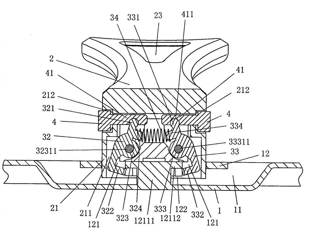
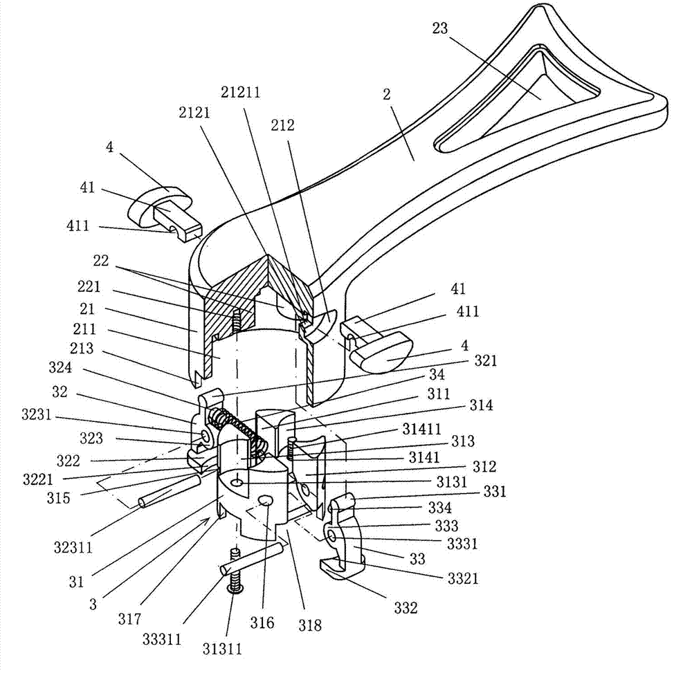
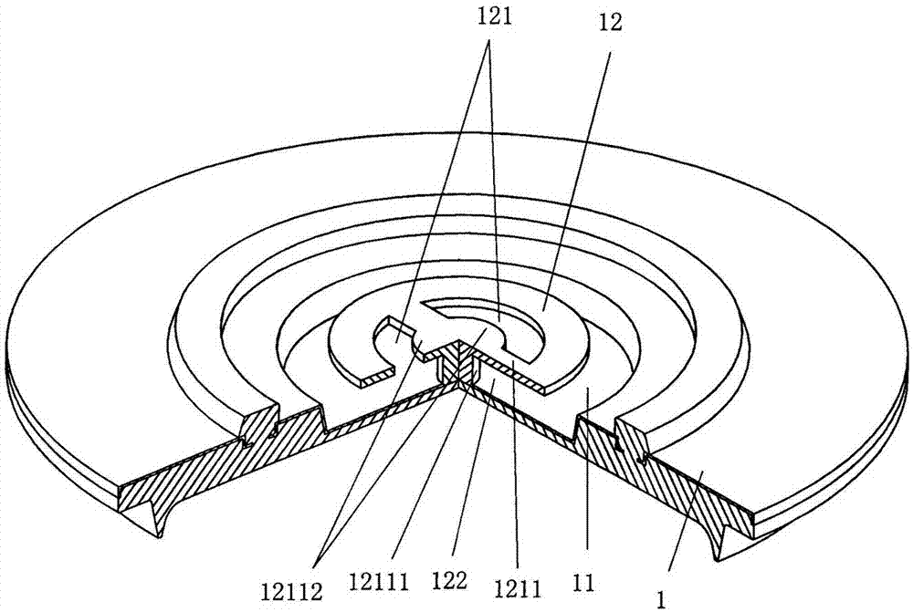
[0024] See figure 1 , image 3 with Figure 4 , A pot cover body 1 is provided, and the side facing upward in the use state of the pot cover ...


PUM


Abstract

The invention discloses a pot cover structure, and belongs to the technical field of cooking utensils. The pot cover structure comprises a pot cover body and a handle body. The pot cover structure is characterized in that the central position of one upward side of the pot cover body is provided with a concave cavity, wherein a pot cover lifting plate is arranged in the concave cavity, the pot cover lifting plate is provided with a pair of connecting seat matching cavities, the space between the pot cover lifting plate and the bottom wall of the concave cavity forms a clamping jaw moving and rising cavity, and a lifting plate fixing column is arranged at the middle position of a partition plate of the matching cavities and on the side facing the bottom wall of the concave cavity; a pot cover clamping and releasing mechanism connecting seat is arranged at one end of the handle body, wherein the central position of the pot cover clamping and releasing mechanism connecting seat is provided with a latch hook seat cavity, a pot cover clamping and releasing mechanism is arranged in the latch hook seat cavity, the pot cover clamping and releasing mechanism connecting seat is provided with a pair of buttons in a matched mode, and the buttons are distributed in a face-to-face state and extend into the latch hook seat cavity to be matched with the pot cover clamping and releasing mechanism. According to the pot cover structure, the number of handle bodies is reduced, resources are saved, and the pot cover structure is convenient to use and store in a standby state.

Description

Technical field [0001] The invention belongs to the technical field of cooking appliances, and specifically relates to a pot cover structure. Background technique [0002] In order to facilitate the lifting of the lid, the lid is usually equipped with a knob or handle. For example, the Chinese Patent Authorization Announcement No. CN202457942U recommends "a handle and a lid with a handle". The technical effect of this patent First, it is convenient to hold and avoid hot hands; second, because the two ends of the grip part of the handle are respectively formed with a head and a standing part, so that the pot can be placed on the stove in a vertical state when the lid leaves the pot body Therefore, hygiene can be ensured. For details, please refer to paragraphs 0002-0018 of the patent specification. However, this patented solution has the following shortcomings: First, because the handle body (the patented grip portion) is permanently fixed with the pot cover, that is to say, the ...

Claims


Application Information

Patent Timeline
Patent Type & Authority Applications(China)
IPC IPC(8): A47J36/06A47J45/07
Inventor 金钟文
Owner CHANGSHU KASMAIN
Why Eureka
Try Eureka