Closestool capable of conducting air exhaust deodorization and vacuum-assisted flushing

A vacuum-assisted, flushing toilet technology, which is applied to water supply devices, flushing equipment with water tanks, sanitary equipment for toilets, etc., can solve the problems of water storage reduction, water tank volume compression, and limited vacuum effect, and achieve air pressure reduction. The effect of small size, noise reduction and energy consumption reduction

Inactive Publication Date: 2014-03-05
BEIJING UNIV OF TECH
View PDF7 Cites 14 Cited by
  • Summary
  • Abstract
  • Description
  • Claims
  • Application Information

AI Technical Summary

Problems solved by technology

[0008] However, for vacuum-assisted flushing toilets of this structure, the air channel must be open during the non-flushing time to prevent all the water in the toilet from being siphoned, and the vacuum source area is limited in size, and the water inlet valve of the toilet tank is simultaneously lowered. On, the water level drop gradient is suppressed by water inflow
Therefore, the vacuum effect generated by the vacuum source area is very limited only by the drop of the water level, and the effect of vacuum-assisted flushing cannot achieve the desired effect.
The layout of the vacuum source area will inevitably reduce the volume of the water tank and reduce the water storage capacity for flushing, thus affecting the flushing pressure and flushing effect of the toilet.

Method used


Image

  • Closestool capable of conducting air exhaust deodorization and vacuum-assisted flushing
  • Closestool capable of conducting air exhaust deodorization and vacuum-assisted flushing
  • Closestool capable of conducting air exhaust deodorization and vacuum-assisted flushing

Examples


Embodiment Construction

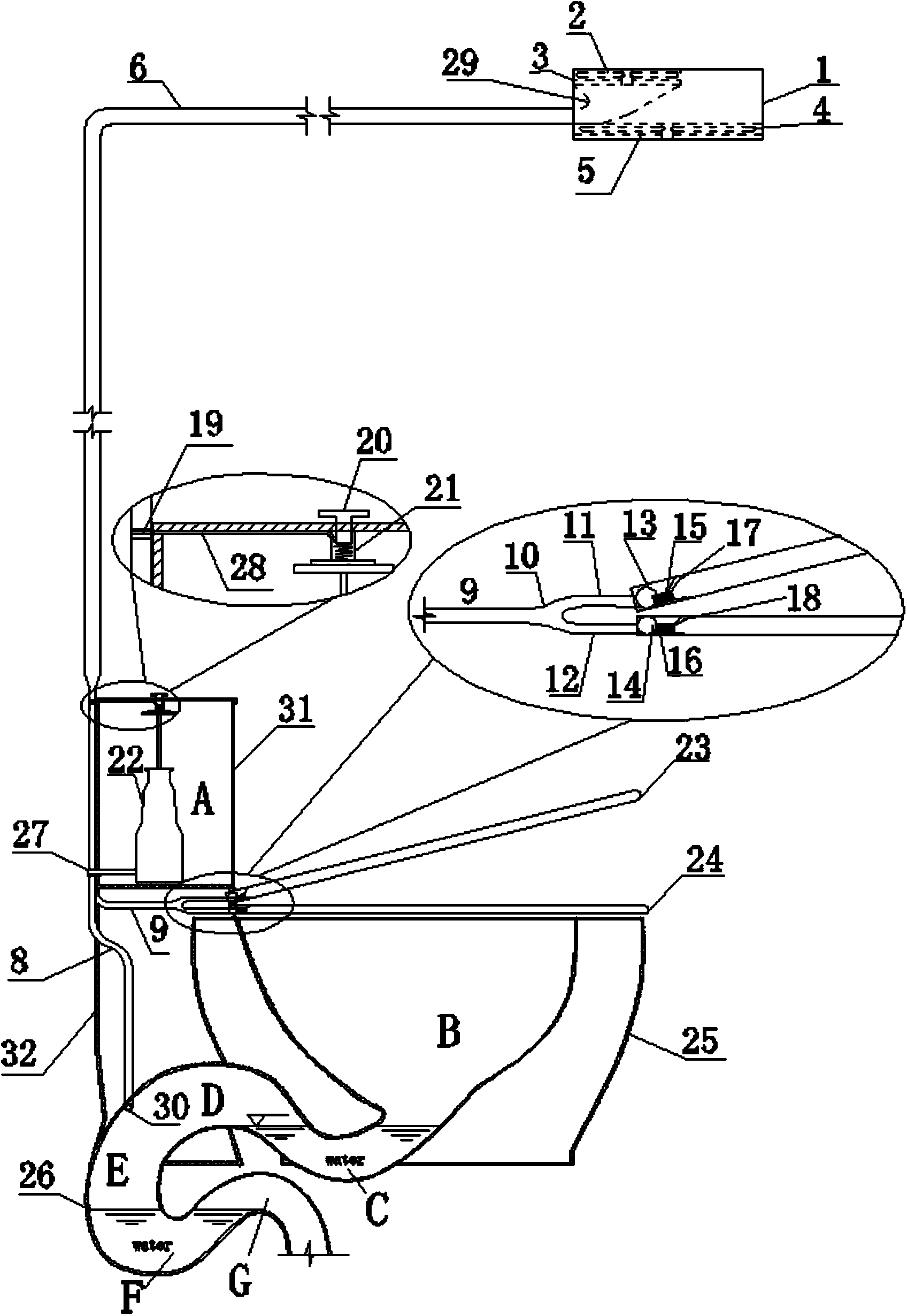
[0030] Attached below Figure 1 to Figure 7 The embodiments of the present invention are described in detail.

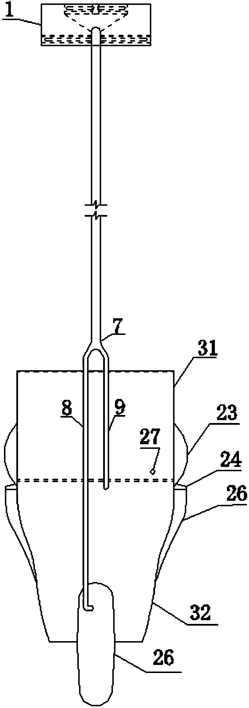
[0031] The structure diagram of the toilet of the present invention is as follows Figure 1 to Figure 7 As shown, the overall structure of the toilet is mainly composed of an exhaust air suction system, a drainage system, a toilet and a control system, and the exhaust air suction system is used in the toilet's exhaust air deodorization and vacuum-assisted water pumping procedures.

[0032] The specific implementation steps are as follows:

[0033] When the toilet is not in use, pass the toilet exhaust fan switch k 2 The lower fan 4 controlling the double-layer exhaust fan 1 exhausts and ventilates the toilet.

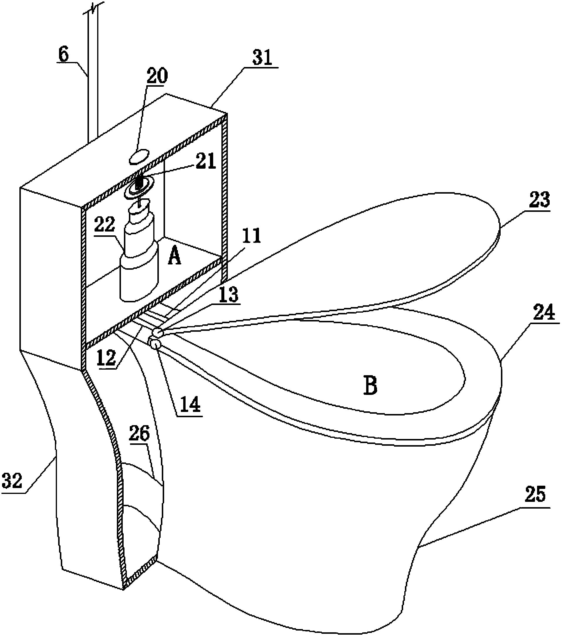
[0034] When the toilet is in use, the upper shaft 13 can be rotated by opening and closing the toilet cover 23 to control the operation of the exhaust air suction system.

[0035] Step 1: When using the toilet, open the toilet cover 23, and the upper shaft 13 of the t...


PUM


Abstract

The invention provides a closestool capable of conducting air exhaust deodorization and vacuum-assisted flushing, and belongs to the technical field of daily living articles. The closestool is improved on the basis of a traditional closestool so that the disadvantages and the defects in the prior art in terms of the closestool deodorization technology and the vacuum-assisted flushing can be overcome, and a double-layer air exhaust fan serves as a power source for an air exhaust deodorization system of the whole closestool and a vacuum-assisted flushing system of the whole closestool. The air exhaust deodorization technology which saves energy and is environmentally friendly is provided for air exhaust deodorization of the closestool. Flushing is assisted by vacuum so that water resources can be saved. An existing air exhaust device in a toilet is improved and combined with the closestool to form a set of system, namely, the closestool capable of conducting air exhaust deodorization and vacuum-assisted flushing. The air exhaust deodorization effect and the vacuum-assisted flushing effect can be achieved while no excessive devices are additionally arranged on the closestool to occupy space in the toilet. The closestool is improved so that the closestool can have the air exhaust deodorization function and the vacuum-assisted flushing function, odorous gas can not be left after people relieve the bowels due to the air exhaust deodorization function, and water resources are saved due to the vacuum-assisted flushing function.

Description

Technical field [0001] The invention relates to a vacuum-assisted flushing toilet with exhaust air and deodorization. The invention is based on the traditional toilet and is improved. The toilet is transformed into a toilet with the functions of exhaust air, deodorization and vacuum assisted flushing. It does not leave unpleasant gases in the bathroom after the convenience of people, and the use of vacuum assisted flushing saves water resources, so that the use of toilets can achieve a comfortable and economical concept. Background technique [0002] 1) Toilet deodorization technology [0003] The current deodorization technology used in toilets is composed of deodorant, centrifugal exhaust fan and circuit. [0004] Principle: Deodorization starts immediately after seating, and deodorization continues to work for 1 min after leaving the seat. The exhaust gas from the human body is pumped out of the ceramic cavity by the centrifugal exhaust fan to produce chemical and physical react...

Claims


Application Information

Patent Timeline
Patent Type & Authority Applications(China)
IPC IPC(8): E03D9/052E03D3/10A47K13/30
Inventor 张文学曾亚陈壮刘海陆李增银谢全懿
Owner BEIJING UNIV OF TECH
Why Eureka
Try Eureka