
System and method of automatic stage lighting positioning and tracking based on micro inertial sensor

An inertial sensor and stage lighting technology, applied in the direction of light source, electric light source, electric light circuit layout, etc., can solve the problems of high technical requirements, increased computer computing time, slowness, etc., achieve fast and accurate automatic control process, and increase the stage effect , the effect of reducing usage

Inactive Publication Date: 2014-03-05
SENODIA TECH (SHANGHAI) CO LTD
View PDF14 Cites 41 Cited by
  • Summary
  • Abstract
  • Description
  • Claims
  • Application Information

AI Technical Summary

Problems solved by technology

[0004] Through manual control, the problem is: not only to adjust the direction of illumination and brightness, long-term operation will cause fatigue or slow response, and the number of controllable lamps is limited
[0005] As stated in the Chinese invention patent with the publication number CN1229893, professionals use computers to monitor the working status of various projection lights in real time. The problems are: high professional technical requirements, low automation, high labor intensity, and easy fatigue;
[0006] The Chinese invention patent with the publication number CN1090961 discloses a manual computer combined console for lights, which can pre-set the actor’s action route, and use the computer to set the tracking route of the light. The problem is: the tracking function is not enough. Flexible, creates great constraints on the performance of the actors
[0008] The problems in the existing technology are: firstly, for the pressure sensor, it is necessary to arrange the pressure sensor in the whole venue, the cost is huge, and it is not applicable to the situation where the actor appears from the air
Especially in some large-scale stage plays, large-scale props may hinder the use of some optical sensors, or reduce the efficiency of sensors; finally, a lot of image processing work is required through image detection and other positioning methods, and the processing capacity of the on-site computer is required. high
Although theoretically possible, the cost is extremely high and it is difficult to achieve real-time
Moreover, it is difficult to track multiple different moving targets. Even if it can be achieved, it requires a very complicated calculation method, which increases the computing time of the computer and reduces the efficiency and sensitivity of automatic tracking.

Method used


Image

  • System and method of automatic stage lighting positioning and tracking based on micro inertial sensor
  • System and method of automatic stage lighting positioning and tracking based on micro inertial sensor
  • System and method of automatic stage lighting positioning and tracking based on micro inertial sensor

Examples


Embodiment Construction

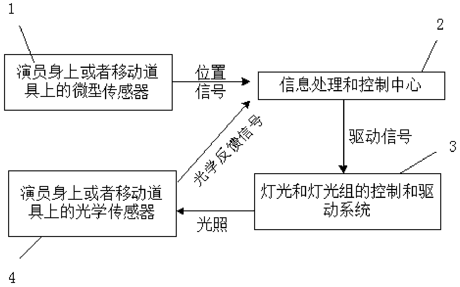
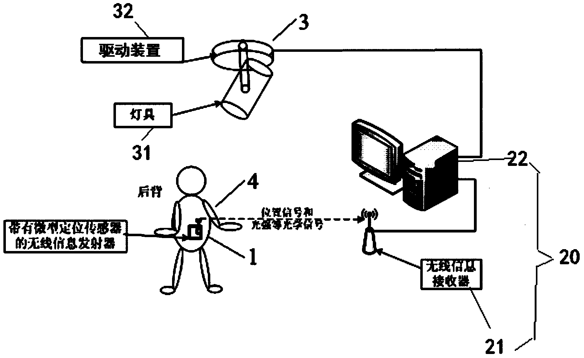
[0033] Such as Figure 1A As shown, the present invention provides a stage lighting automatic positioning and tracking system based on a miniature gyroscope sensor, which includes a miniature inertial sensor (IMU) 1, an information processing and control center 2, a lighting device 3 that can adjust optical parameters, and optical sensor 4,

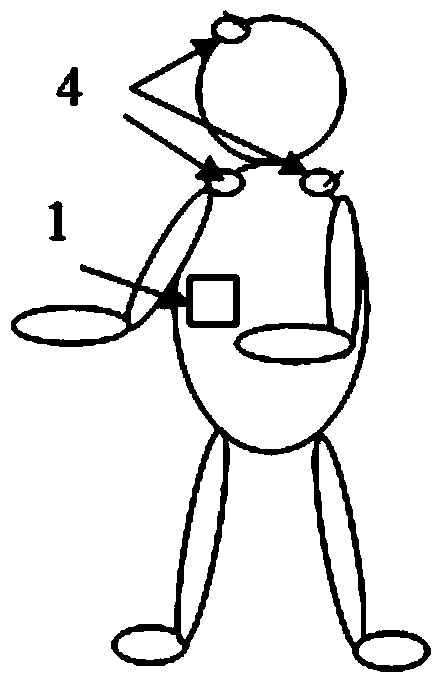
[0034] Such as Figure 1B As shown, the miniature inertial sensor 1 and the optical sensor 4 containing the miniature gyroscope and miniature accelerometer are respectively installed on the actors or moving props, and transmit the position information to the information through wireless means (such as: WIFI, Bluetooth, Zigbee, etc.) The processing and control center 2, the information processing and control center 2 obtains the optimized optical parameter information of the corresponding lamp through calculation, and transmits this information to the driving device on the lamp in a wireless or wired manner, thereby adjusting the adjustabl...


PUM


Abstract

The invention relates to an automatic stage lighting positioning and tracking system based on a micro inertial sensor. The automatic stage lighting positioning and tracking system based on the micro inertial sensor comprises a lighting device capable of adjusting optical parameters; the device comprises a lamp with an adjustable brightness and rotation angle, an adjusting device for adjusting the lamp brightness, and a drive device for driving the lamp to change the rotation angle; the system also comprises the micro inertial sensor which is arranged on a tracked object, is used to generate position and attitude change information of the tracked object, and sends the information wirelessly; the system also comprises an information processing and control center; the information processing and control center comprises a wireless receiving device for receiving position information of the micro inertial sensor, and a drive control signal and / or an adjustment control signal of the adjusting device for driving the drive device, wherein the drive control signal and / or the adjustment control signal are derived according to the position information. According to the invention, the system, based on the stage prop or the optical sensor on the actor, determines whether the light tracking is accurate, and sends relevant information back to the computer for the precision adjustment, so that the specific stage lighting can be accurately traced to the specific actor and prop.

Description

technical field [0001] The invention relates to a technology for automatically controlling stage lights, in particular to a system and method for controlling and adjusting stage lights. Background technique [0002] On the stage of various large-scale activities, various dynamic and colorful neon lights can set off and show a dreamlike stage atmosphere. Not just a platform, but three-dimensional stages with various stairs and other scenes can be found everywhere. Therefore, it is difficult to capture the actions of specific actors or props with specific lighting in a timely and accurate manner in such an increasingly complex stage situation. . [0003] At present, there are mainly the following technical methods to realize real-time tracking of actors on a two-dimensional plane stage. [0004] Through manual control, the problem is: not only to adjust the direction of illumination and brightness, long-term operation will cause fatigue or slow response, and the number of co...

Claims


Application Information

Patent Timeline
Patent Type & Authority Applications(China)
IPC IPC(8): H05B37/02
Inventor 付世
Owner SENODIA TECH (SHANGHAI) CO LTD
Learn More