
Manual centering mechanism

A centering mechanism and handwheel technology, applied in positioning devices, metal processing machinery parts, clamping, etc., can solve the problems of high labor intensity for operators, troublesome alignment and positioning, and low work efficiency, and achieve simple structure and easy operation. Convenience and the effect of reducing labor intensity

Active Publication Date: 2016-05-18
通用技术集团大连机床有限责任公司
View PDF5 Cites 0 Cited by
  • Summary
  • Abstract
  • Description
  • Claims
  • Application Information

AI Technical Summary

Problems solved by technology

For workpieces with casting holes on the outside, there is no mechanism for aligning and positioning them using the holes. Therefore, aligning and positioning such workpieces is troublesome, time-consuming, labor-intensive, and labor-intensive for operators.

Method used


Image

  • Manual centering mechanism
  • Manual centering mechanism

Examples


Embodiment Construction

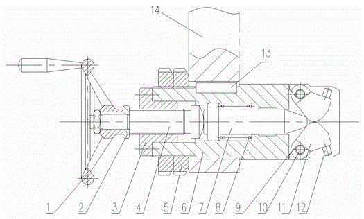
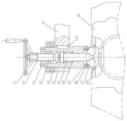
[0009] Such as figure 1 As shown: 14 is a bracket, and the bracket 14 is installed at the clamping position of the workpiece on the machining production line, and a driving mechanism is provided to drive the bracket 14 to move relatively. A guide sleeve 6 is fixed on the bracket 14, and one end of the guide sleeve 6 is fixed with an end cover 3 by bolts, the inner hole of the end cover 3 is threadedly connected with a screw rod 4, and the outer end of the screw rod 4 is connected with a hand wheel 1 and Pad 2. The inner end of the screw rod 4 leans against the end of the top shaft 7 located in the guide sleeve 6, and the other end of the top shaft 7 is connected with a rotating claw 11, and the rotating claw 11 is connected to the end of the guide sleeve 6 through a pin shaft 10. Rotating pawl 11 is positioned at the opening of guide sleeve 6 ends, is sleeved with the torsion spring 9 that is pressed to the inboard rotating pawl 11 on pin shaft 10, and the outside of rotating...


PUM


Abstract

The invention provides a manual centering mechanism which comprises a guide sleeve. The guide sleeve is installed on a support. One end of the guide sleeve is provided with an end cover. An inner hole of the end cover is connected with a screw rod in a threaded mode. The outer end of the screw rod is connected with a hand wheel. The inner end of the screw rod abuts against the end of a push shaft arranged in the guide sleeve. The other end of the push shaft is connected with rotating claws connected to the end portion of the guide sleeve through hinge pins. The rotating claws are arranged in an opening of the end portion of the guide sleeve. The hinge pins are provided with torsion springs in a sleeved mode, wherein the torsion springs press the rotating claws to the inner side. The outer sides of the rotating claws are connected with push nails. The rotating claws are two in number and are symmetrically arranged. A spring is arranged between the inner end of the push shaft and the step of the inner hole of the guide sleeve. The manual centering mechanism has the advantages of being simple in structure and convenient to operate, utilizing a cast hole in the outer side of a work-piece to carry out centering and locating, improving the work efficiency and lowering the labor intensity.

Description

technical field [0001] The invention relates to a manual centering mechanism, which is used for manual alignment and positioning of workpieces with casting holes on the outside during machining. Background technique [0002] The centering mechanism is one of the commonly used mechanical structures in the machining industry, and its function is to adjust the workpiece from an irregular position to a specific posture. For workpieces with casting holes on the outside, there is currently no mechanism for aligning and positioning them. Therefore, aligning and positioning such workpieces is troublesome, time-consuming, labor-intensive, low in work efficiency, and labor-intensive for operators. Contents of the invention [0003] The purpose of the present invention is to provide a manual centering mechanism with simple structure, convenient operation, using the casting hole on the outside of the workpiece for alignment and positioning, improving work efficiency and reducing labor...

Claims


Application Information

Patent Timeline
Patent Type & Authority Patents(China)
IPC IPC(8): B23Q3/00
CPCB23Q3/183
Inventor 祝恩临贺钧彭小敢房宸宾丛琳
Owner 通用技术集团大连机床有限责任公司
Learn More