
Drill rod pilot device

A technology for drill pipes and drill bits, which is applied in the direction of drill pipes, drill pipes, drilling equipment, etc., and can solve the problems of easy deflection of pile holes, quality accidents, quality problems, etc., and achieve good guiding effect, easy assembly, and simple structure Effect

Pending Publication Date: 2020-11-20
SHANDONG ZHENGYUAN CONSTR ENG
View PDF0 Cites 0 Cited by
  • Summary
  • Abstract
  • Description
  • Claims
  • Application Information

AI Technical Summary

Problems solved by technology

[0005] The construction of bored piles has two types of mud retaining method and full casing construction method due to the different formation of the selected retaining wall. Rotary drilling rig and submersible drilling rig are two commonly used construction equipment for mud retaining bored piles. Rotary drilling rig or When the submersible drilling rig is drilling, it mainly relies on the drill bit to guide and control the verticality deviation of the pile hole. However, due to the limited steering ability of the drill bit, the pile hole is prone to deflection. When the deflection is large, the reinforcement cage cannot be placed in place. , in severe cases, even the catheter cannot be lowered, resulting in quality problems or quality accidents

Method used


Image

  • Drill rod pilot device
  • Drill rod pilot device
  • Drill rod pilot device

Examples


Embodiment

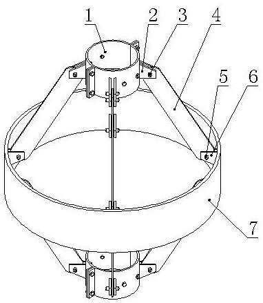
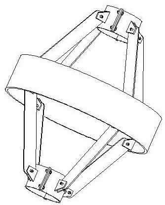
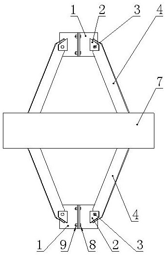
[0036] Such as Figure 1-Figure 5 As shown, a drill pipe guiding device includes a guiding steel ring 7, the diameter of which is slightly smaller than or equal to the diameter of the drill bit, and a fixed joint 1 is coaxially arranged above and below the guiding steel ring 7; The inner diameter of the fixed section 1 is equivalent to the outer diameter of the drill pipe 11, and is used for coaxial fixing on the drill pipe 11; the outer circumference of the fixed section 1 is evenly distributed and fixedly welded with 4 hinge lugs I2, and the inner circumference of the guiding steel ring 7 is welded There are two sets of hinge ears Ⅱ6, upper and lower, and the number of hinge ears Ⅱ6 in each group is 4, and the circumference is evenly distributed; it also includes 8 connecting steel plates 4, the first end of the connecting steel plate 4 is hinged with the hinge ear Ⅰ2, and the connecting steel plate The second end of 4 is hinged with the hinge ear II6, and the hinge structur...


PUM


Abstract

The invention relates to a drill rod pilot device. The device comprises a pilot steel ring, wherein the diameter of the pilot steel ring is slightly smaller than the diameter of a drill bit, fixed joints are coaxially arranged above and below the pilot steel ring, and the fixed joints are used for being coaxially fixed on a drill rod; a plurality of hinge lugs I which are uniformly distributed arearranged on the outer periphery of each fixed joint, an upper group of hinge lugs II and a lower group of hinge lugs II are arranged on the inner periphery of the pilot steel ring, and the number ofeach group of hinge lugs II and the number of hinge lugs I on each fixed joint are equal; and the device further comprises a plurality of connecting steel plates, wherein the first ends of the connecting steel plates are hinged to the hinge lugs I, the second ends of the connecting steel plates are hinged to the hinge lugs II, and the hinge structures are hinged modes which are convenient to disassemble and assemble. When in use, the pilot steel ring is coaxial with the drill bit, the pilot device is driven into a hole along with the drill rod, a certain distance is provided between the pilotsteel ring and the drill bit, when the drill bit drives the drill rod to deflect, the pilot steel ring makes contact with the hole wall, the deflection of the drill rod is forced to be controlled, andthus the purpose of pilot is achieved, the defect that an active pilot device occupies the space of the hole mouth platform is overcome, the structure is simple, and the disassembly and assembly areconvenient.

Description

technical field [0001] The invention relates to the technical field of bored pile engineering, in particular to a drill pipe guiding device. Background technique [0002] Bored cast-in-situ pile refers to a pile formed by mechanically drilling a pile hole in the foundation soil at the engineering site, placing a steel cage in it, and pouring concrete into it. It is a pile defined according to the pile-forming method. pile type. [0003] Bored cast-in-place piles first appeared in the United States in the early 1940s with the successful development of high-power drilling tools. The application of bored piles in my country began in the early 1960s and was first used in bridge and port construction. Today, with the rapid development of science and technology, bored piles are widely used in high-rise, super high-rise buildings and heavy structures, and their design and construction levels have been greatly developed. [0004] Bored piles have the advantages of little harm to th...

Claims


Application Information

Patent Timeline
Patent Type & Authority Applications(China)
IPC IPC(8): E21B17/10E21B7/10
CPCE21B7/10E21B17/1078
Inventor 彭波冯小冬吕海滨赵青海刘世强魏祥江李坤董宜辉
Owner SHANDONG ZHENGYUAN CONSTR ENG
Learn More