
Alignment structure and automatic alignment device for piston pin hole machining

A piston pin hole and automatic technology, applied in positioning devices, metal processing, metal processing equipment, etc., can solve the problems of unsuitable piston processing conditions, long time for single piston alignment, complex equipment structure, etc., and achieve low production cost , reducing the gap between advantages and disadvantages, and the overall structure is simple

Pending Publication Date: 2022-04-22
SICHUAN DANFU ENVIRONMENT TECH CO LTD
View PDF0 Cites 0 Cited by
  • Summary
  • Abstract
  • Description
  • Claims
  • Application Information

AI Technical Summary

Problems solved by technology

[0003] At present, for the alignment of piston pin hole processing, the combination of visual imaging system and servo system is generally used in the industry. The system equipment required by this method is complex in structure, difficult in design, and high in manufacturing cost. The alignment time of the piston is long and the work efficiency is low. It is not suitable for large-scale piston processing conditions and has great limitations.

Method used


Image

  • Alignment structure and automatic alignment device for piston pin hole machining
  • Alignment structure and automatic alignment device for piston pin hole machining
  • Alignment structure and automatic alignment device for piston pin hole machining

Examples


Embodiment Construction

[0030] The following will clearly and completely describe the technical solutions in the embodiments of the present invention with reference to the accompanying drawings in the embodiments of the present invention. Obviously, the described embodiments are only some, not all, embodiments of the present invention. Based on the embodiments of the present invention, all other embodiments obtained by persons of ordinary skill in the art without making creative efforts belong to the protection scope of the present invention.

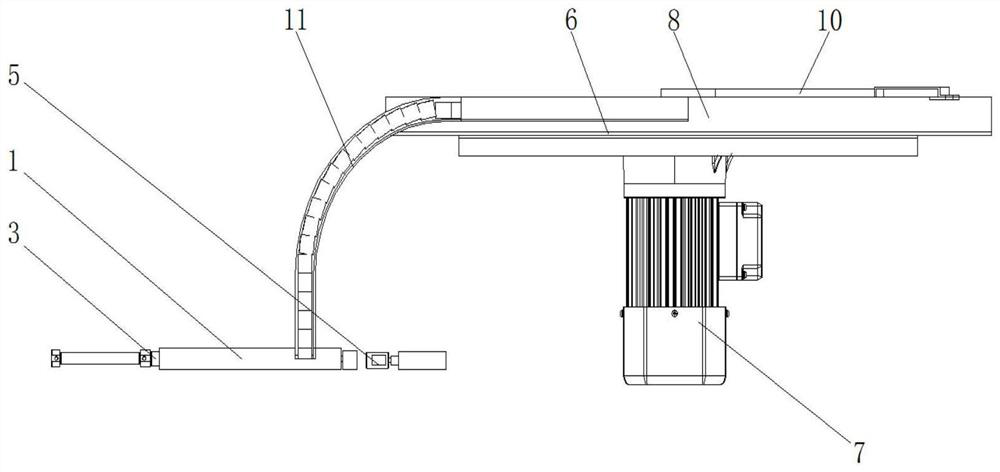
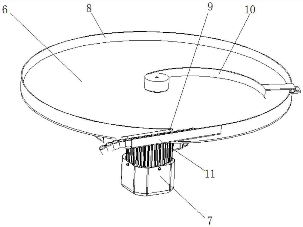
[0031] Such as figure 1 A kind of alignment structure for the machining of piston pin holes is shown, comprising a guide cylinder 1, a feed port 2 is provided on the side wall of the guide cylinder 1, a push rod 3 is arranged inside the guide cylinder 1, and the push rod 3 is connected with the The guide cylinder 1 is slidingly connected. The guide cylinder 1 is provided with a discharge port 4 along the pushing direction of the push rod 3. The piston enters t...


PUM


Abstract

The invention belongs to the technical field of piston machining, provides an alignment structure for piston pin hole machining and an automatic alignment device, and is mainly used for solving the problems that an existing piston alignment structure is complex, the manufacturing cost is high, and the working efficiency is not high. The guide cylinder is arranged in the alignment structure, the material pushing rod is arranged in the guide cylinder, after a piston element enters the guide cylinder through the feeding port, the material pushing rod can be movably inserted into a machined installation cavity in a piston and push the piston to move towards the discharging port, and after the piston is pushed out of the guide cylinder, the material pushing rod is pushed out of the guide cylinder. The piston can automatically rotate and be adjusted to a balanced state under the action of the gravity of the piston, so that the length direction of the mounting cavity of the piston is vertically downward so as to achieve the aim of alignment, the whole structure is simple, the mode is reasonable, the production cost of equipment is low, the piston can be aligned immediately after the piston is completely pushed out by the pushing rod, and the operation is simple, fast and convenient. The single piston is short in alignment period, high in working efficiency and capable of being applied to a machining production line of large-batch piston pin holes.

Description

technical field [0001] The invention belongs to the technical field of piston processing, and more specifically relates to an alignment structure and an automatic alignment device for machining piston pin holes. Background technique [0002] Today, pistons are widely used in engineering components such as engines, compressors, cylinders, and hydraulic cylinders. They have the functions of sealing, transmission, and pressure regulation. They have the advantages of good working performance and low manufacturing cost. When it comes to the piston, it has to be associated with the piston rod. Usually, the piston and the piston rod are connected by the piston pin, which requires processing the installation cavity and the pin hole for the head of the piston rod on the piston. In the process of piston processing, the pin hole is generally processed after milling the mounting cavity; at the same time, in order to ensure the stable connection between the piston and the piston rod and ...

Claims


Application Information

Patent Timeline
Patent Type & Authority Applications(China)
IPC IPC(8): B23Q3/18B23Q7/06
CPCB23Q3/186B23Q7/06
Inventor 王东舒向东
Owner SICHUAN DANFU ENVIRONMENT TECH CO LTD
Learn More