A Leakage Detection and Location Method of Oil Pipeline Based on Synthetic Signals

A positioning method and leak detection technology, which is applied in the pipeline system, by measuring the increase and deceleration rate of the fluid, and using the liquid/vacuum degree to measure the liquid tightness, etc., can solve the problems of difficult identification, unclear pressure inflection point, leak location, etc.

Inactive Publication Date: 2017-01-11
CHINA UNIV OF PETROLEUM (EAST CHINA)
View PDF6 Cites 0 Cited by
  • Summary
  • Abstract
  • Description
  • Claims
  • Application Information

AI Technical Summary

Problems solved by technology

[0004] The existing negative pressure wave method only locates the leak according to the pressure change at both ends of the pipeline. Although the flow signal is also detected on the pipeline, it is only used as the basis for the leakage alarm and does not perform location.
The pressure change is related to the equipment at both ends of the pipeline. In extreme cases, such as when the end of the pipeline is an oil tank, the pressure at the end of the pipeline is always fixed at the pressure in the oil tank, and the negative pressure wave caused by the leakage cannot be displayed at all.
In addition, for small leaks and slow releases, the pressure inflection point is not obvious and difficult to identify

Method used


Image

  • A Leakage Detection and Location Method of Oil Pipeline Based on Synthetic Signals
  • A Leakage Detection and Location Method of Oil Pipeline Based on Synthetic Signals
  • A Leakage Detection and Location Method of Oil Pipeline Based on Synthetic Signals

Examples


Embodiment Construction

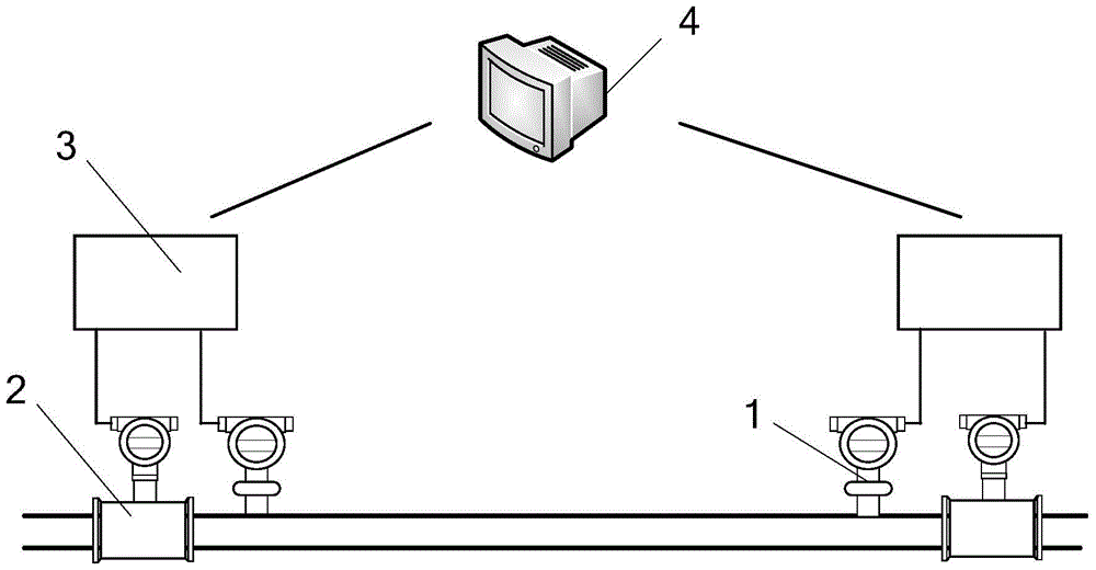
[0036] In this example, refer to Figure 1 to Figure 5 As shown, a method for detecting and locating oil pipeline leaks based on integrated signals, the hardware structure used in the method for detecting and locating oil pipeline leaks based on integrated signals includes a pressure transmitter 1, a flow meter 2, a data collector 3 and Control Terminal 4. The flow meter is preferably a mass flow meter.

[0037] Specifically include the following steps:

[0038] A. Data acquisition and integrated signal calculation

[0039] 1) The pressure and flow at the beginning and end of the pipeline are converted into electrical signals by the pressure transmitter 1 and the flow meter 2, collected by the data collector 3, and the data are transmitted to the control terminal 4 for display processing;
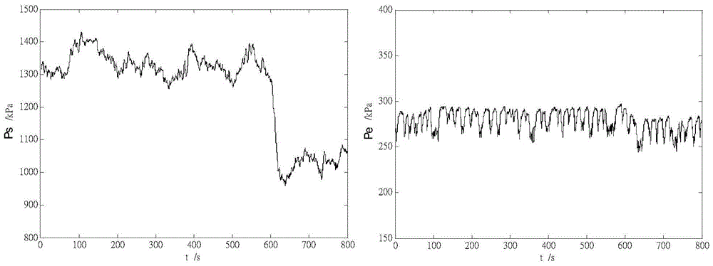
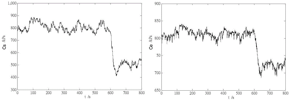
[0040] 2) Collect the output values ​​of the pressure transmitter 1 and the flowmeter 2 at the beginning and end of a pipeline respectively, and send them to the control terminal 4. Let ...


PUM


Abstract

The invention discloses an oil pipeline leakage detection and positioning method based on comprehensive signals. The method oil pipeline leakage detection and positioning method based on comprehensive signals can solve the problems that a single pressure signal is limited by pipeline tail end devices and can hardly detect the pressure inflection point and under the conditions of small leakage and slow leakage, inflection point features of the pressure signal are not prominent in a negative wave pressure method. According to the technical scheme, pressure signals and flow signals in the leakage transient process are combined into new comprehensive signals and variation of the comprehensive signals is monitored. Whether leakage exists or not is judged according to existence of abnormities and leakage position calculation is carried out by recognizing the comprehensive signals. Compared with the negative wave method, limitation by devices at the two ends of the pipeline does not exist and the oil pipeline leakage detection and positioning method is especially suitable for working conditions that oil tanks are arranged at the tail ends of the pipeline and the like. As the comprehensive signals are adopted, the inflection point features of the leakage signal can be effectively highlighted and the oil pipeline leakage detection and positioning method is also suitable for detection and positioning of small leakage and slow leakage.

Description

technical field [0001] The invention relates to a method for detecting and locating oil pipeline leakage based on integrated signals. Background technique [0002] Oil pipeline is an important way of oil transportation in our country, so oil pipeline leakage detection and location has always been a technical problem in history. Pipeline leak detection and location methods are roughly divided into four categories. The first category is based on manual inspection methods. This type of method has the characteristics of high positioning accuracy and low false alarm rate, but it cannot detect leaks in time, and the detection can only be carried out intermittently. The second type is the in-pipe leak detection method based on ultrasonic, magnetic flux, camera and other technologies. This type of method has high positioning accuracy and low false alarm rate, but cannot realize online detection. Because the detection ball drifts with the medium in the pipe, it is prone to blockage ...

Claims


Application Information

Patent Timeline
Patent Type & Authority Patents(China)
IPC IPC(8): G01M3/26F17D5/02
Inventor 孙良
Owner CHINA UNIV OF PETROLEUM (EAST CHINA)
Why Eureka
Try Eureka