Displaying device

A display device and display panel technology, which is applied in nonlinear optics, instruments, optics, etc., can solve problems affecting the optical quality of the light-transmitting area of ​​the display panel, and achieve the effect of improving adverse effects

Inactive Publication Date: 2014-03-12
AU OPTRONICS CORP
View PDF0 Cites 9 Cited by
  • Summary
  • Abstract
  • Description
  • Claims
  • Application Information

AI Technical Summary

Problems solved by technology

However, because the air bubble strip 170 overlaps with the first substrate 141 and exceeds the scope of the light-shielding area 182, the air bubble strip 170 will affect the optical quality of the display panel 140 and the light-transmitting area (not labeled) of the cover glass 110

Method used


Image

  • Displaying device
  • Displaying device
  • Displaying device

Examples


Embodiment Construction

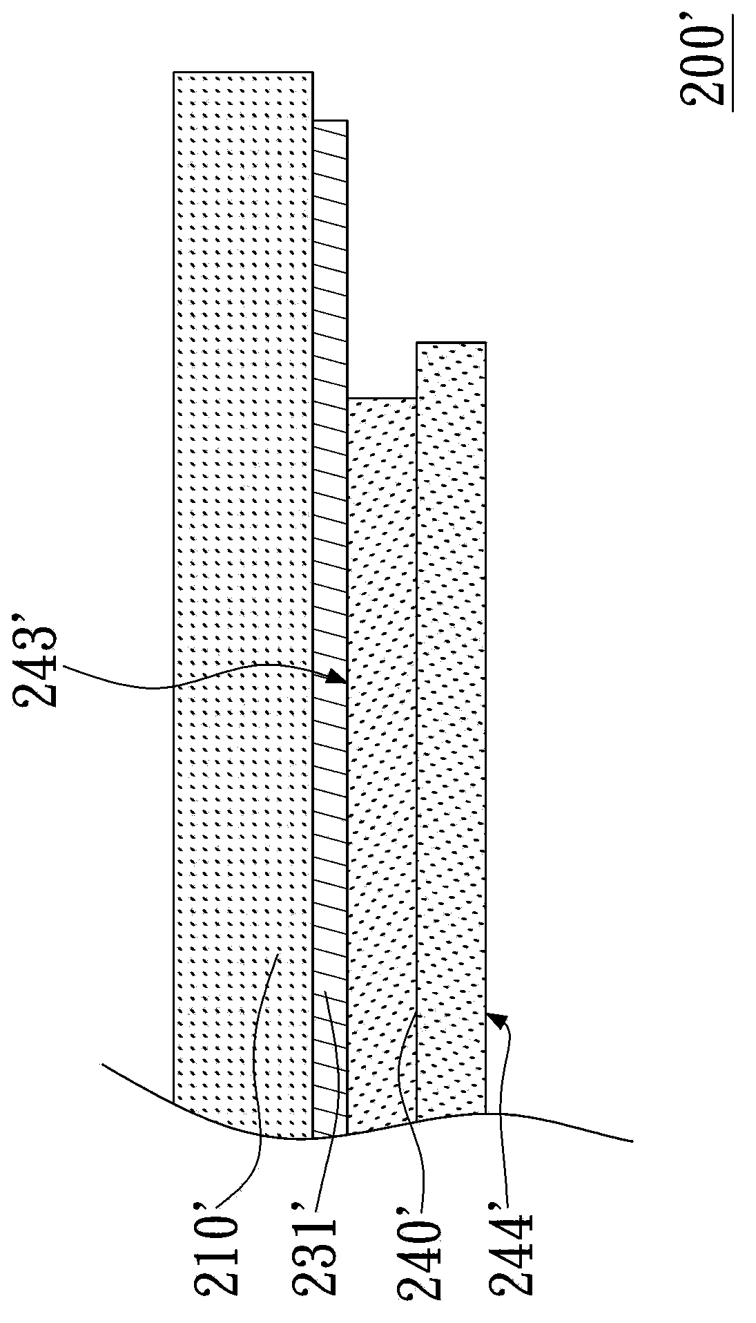
[0039] Please refer to figure 2 , figure 2 What is shown is a schematic cross-sectional view of a display device according to a preferred embodiment of the present invention. The display device 200' includes a display panel 240', a cover 210' and a first polarizer 231'. The display panel 240' has a first surface 243' and a second surface 244' opposite to each other. The cover body 210' covers the first surface 243', and the area of ​​the cover body 210' is larger than that of the first surface 243'. The first polarizer 231' is attached to the cover body 210' and is located between the cover body 210' and the first surface 243', and the area of ​​the first polarizer 231' is larger than that of the first surface 243'.

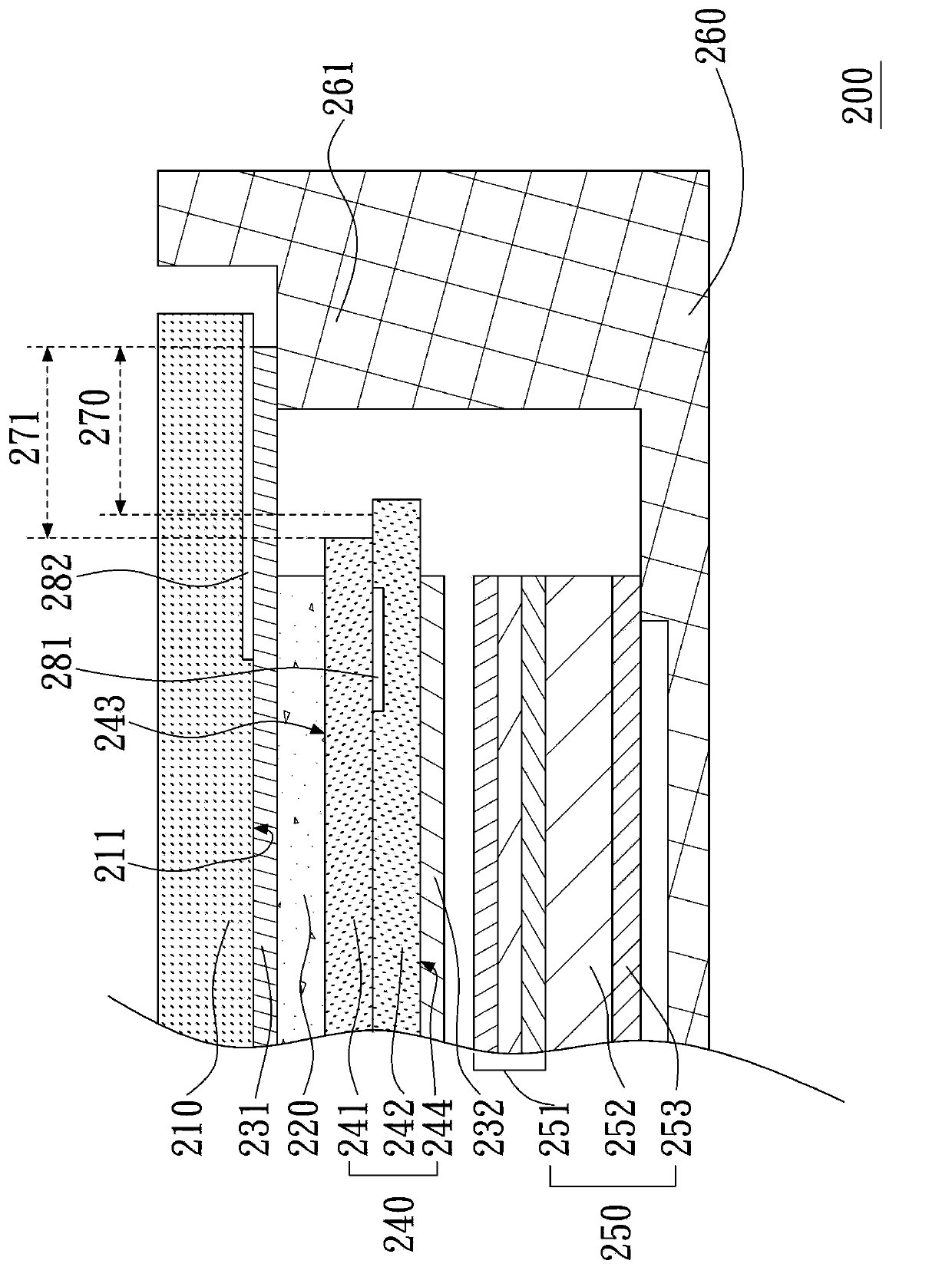
[0040] Please refer to image 3 , image 3 What is shown is a schematic cross-sectional view of a display device according to another preferred embodiment of the present invention. The display device 200 has a protective glass 210 , a first polarizer 231 ...


PUM


Abstract

The invention provides a displaying device which comprises a display panel, a shield body and a first polaroid, wherein the display panel is provided with a first surface and a second surface which are opposite to each other, the shield body covers the first surface, the area of the shield body is larger than the area of the first surface, the first polaroid is attached to the shield body and located between the shield body and the first surface, and the area of the first polaroid is larger than the area of the first surface. Compared with the prior art, the displaying device has the advantage that the negative influence of a bubble band generated on the edge of the first polaroid on optical quality is avoided to a certain degree.

Description

technical field [0001] The present invention relates to a display device, and in particular to a display device with a cover lens. Background technique [0002] Please refer to figure 1 , figure 1 What is shown is a schematic cross-sectional view of a conventional display device. The conventional display device 100 has a cover glass 110 , a first polarizer 131 , a second polarizer 132 , a display panel 140 , a backlight module 150 and a frame 160 . The protective glass 110 is used as a cover for covering the display panel 140 . The display panel 140 includes a first substrate 141 and a second substrate 142, the first substrate 141 and the second substrate 142 are superimposed on each other with a liquid crystal layer (not shown in the figure) sandwiched between them, the second substrate 142 has The light-shielding area 181 is disposed at the edge of the superposed surface of the second substrate 142 and the first substrate 141 . The first substrate 141 has a color filt...

Claims


Application Information

Patent Timeline
Patent Type & Authority Applications(China)
IPC IPC(8): G02F1/1335
Inventor 郑景鸿
Owner AU OPTRONICS CORP
Why Eureka
Try Eureka