Rotary shoe rack

A rotating and rotating rack technology, applied in the field of shoe racks, can solve the problems of being easily contaminated with dust, difficult to pick and place, and occupy a large space, and achieve the effect of reducing the floor space, placing orderly, and utilizing space.

Inactive Publication Date: 2014-03-19
SHANGHAI DIANJI UNIV
View PDF6 Cites 8 Cited by
  • Summary
  • Abstract
  • Description
  • Claims
  • Application Information

AI Technical Summary

Problems solved by technology

[0002] At present, the shoe racks sold on the market and custom-made for families all adopt a box-type structure. The shoe rack with this traditional structure takes up a lot of space, is not easy to pick and place, and is easy to be contaminated with dust.

Method used


Image

  • Rotary shoe rack
  • Rotary shoe rack
  • Rotary shoe rack

Examples


Embodiment Construction

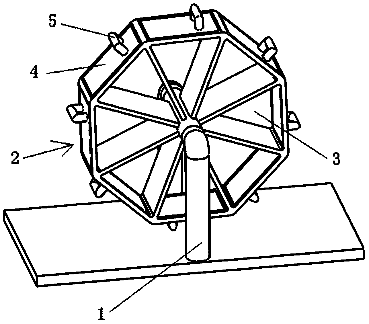
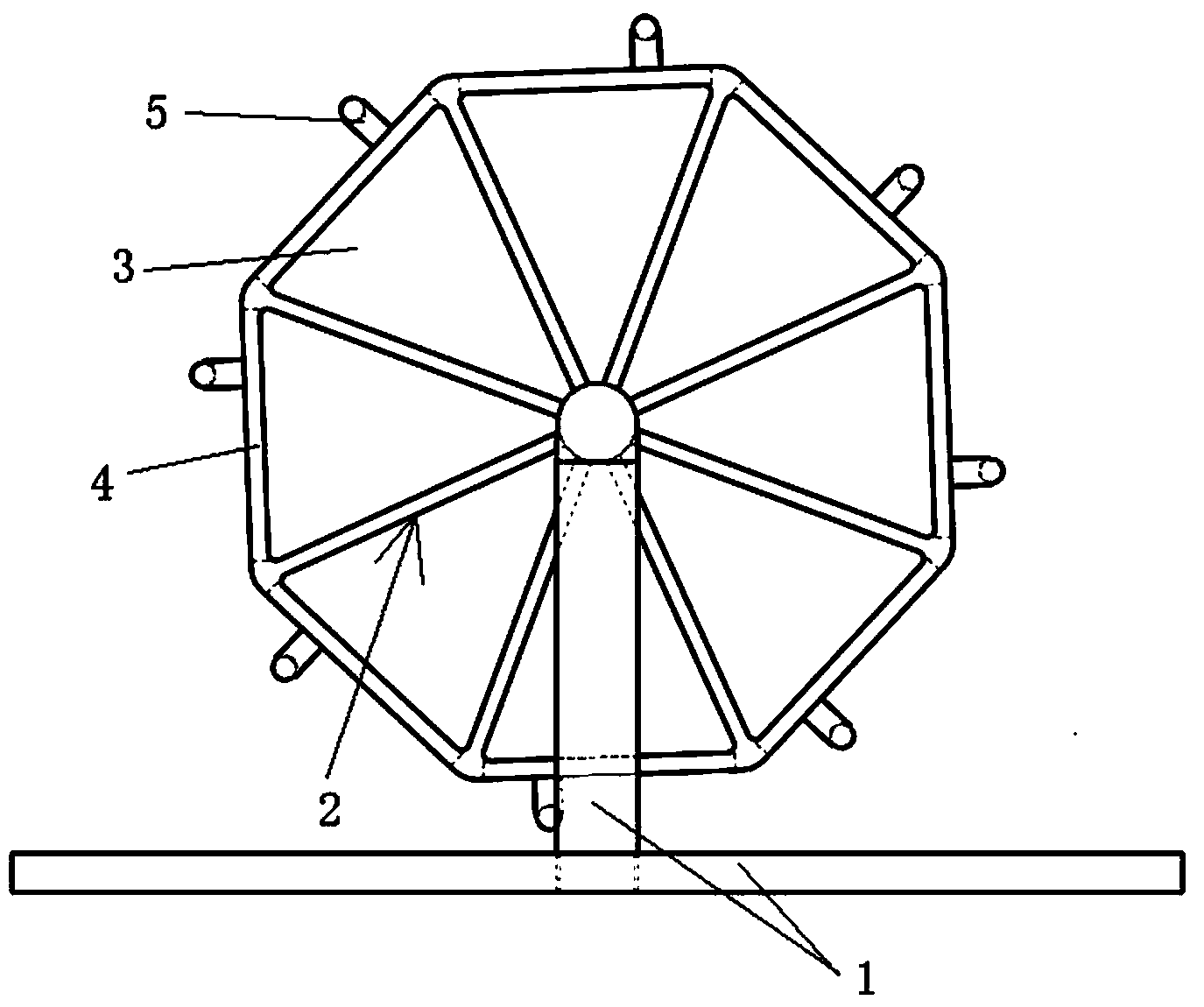
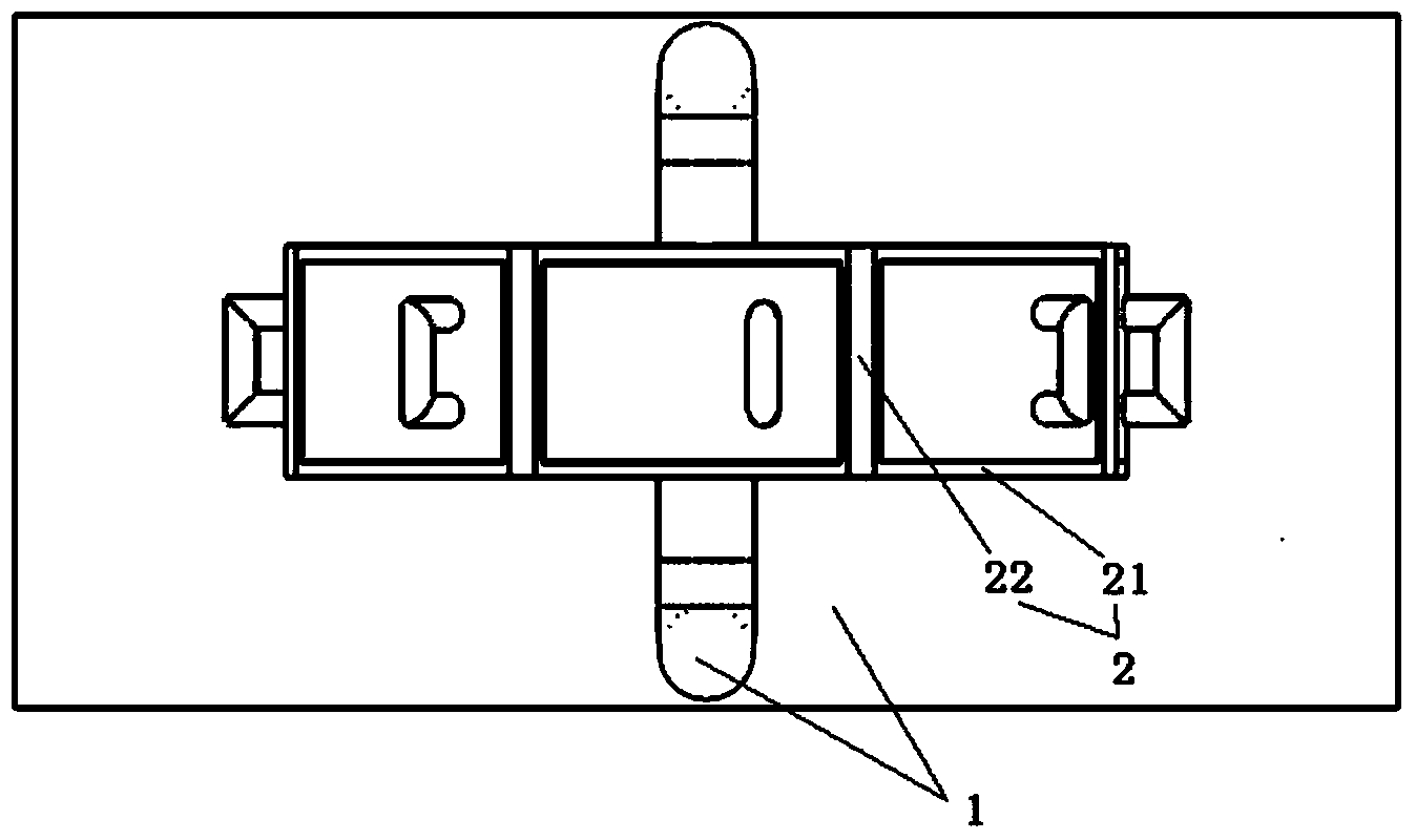
[0015] Figure 1 ~ Figure 3 A specific embodiment of the rotating shoe rack of the present invention is shown. The structure of the rotating shoe rack is very similar to that of a Ferris wheel. A rotating frame 2 that rotates in a vertical plane, and the rotating frame 2 is provided with eight shoe storage chambers 3 that are spaced apart from each other and can place shoes, and eight chambers for opening / closing the shoe storage chambers Door 4, said eight chamber doors 4 correspond to said eight shoe storage chambers 3 one by one.

[0016] During specific application, the user can turn the rotating frame 2, open one or several chamber doors 4 installed on the rotating frame 2, place the shoes in the corresponding shoe storage chambers 3, and then close the opened chamber doors 4 Can. In order to make the shoes be placed more orderly, in this example, each shoe storage cavity 3 is set as a space just enough to accommodate a pair of shoes.

[0017] Refer again Figure 1 ~ ...


PUM


Abstract

The invention discloses a rotary shoe rack which comprises a support base, wherein a rotating rack which can perform rotating motion in a vertical surface around the own axis is hinged and mounted on the support base; and a plurality of shoe storing cavities which are separated mutually and used for storing shoes as well as a plurality of cavity doors used for opening/closing the shoe storing cavities are arranged on the rotating rack. The rotary shoe rack is simple in structure and convenient to use, and has a quite high space utilization rate.

Description

technical field [0001] The invention relates to the field of daily necessities, in particular to a shoe rack. Background technique [0002] At present, the shoe racks sold on the market and custom-made by families all adopt a box-type structure. The shoe racks with this traditional structure occupy a large space, are not easy to pick and place, and are easy to be contaminated with dust. Contents of the invention [0003] The purpose of the present invention is to solve the above problems and provide a rotary shoe rack with simple structure, convenient use and very high space utilization. [0004] The technical solution of the present invention is: the rotary shoe rack includes a supporting base, a rotating frame capable of rotating around its own axis in a vertical plane is hingedly installed on the supporting base, and a There are: several spaced apart shoe storage chambers capable of placing shoes, and several chamber doors for opening / closing the shoe storage chambers....

Claims


Application Information

Patent Timeline
Patent Type & Authority Applications(China)
IPC IPC(8): A47B49/00A47B61/04A47B96/20
Inventor 杨杰钱俊磊王栋王雪张烨沈彤
Owner SHANGHAI DIANJI UNIV
Why Eureka
Try Eureka