
Self-driven tool box running on rail

A toolbox and self-driven technology, applied in the direction of manufacturing tools, workshop equipment, etc., can solve problems such as lack of time to replenish tools, waste of manpower, and affect work efficiency, so as to speed up work efficiency and work quality, save manpower and material resources, and structure well-designed effects

Active Publication Date: 2015-04-22
HUAQIANG FANGTE WUHU CULTURE TECH CO LTD
View PDF6 Cites 0 Cited by
  • Summary
  • Abstract
  • Description
  • Claims
  • Application Information

AI Technical Summary

Problems solved by technology

[0002] In a general maintenance station or maintenance room, there are often multiple maintenance points, and each maintenance point is in charge of a maintenance worker, and each maintenance worker also has his own tools. However, some tools are not available to every maintenance worker. Yes, such as more expensive tools or some tools that are damaged and have not been replaced in time
When maintenance workers need these tools, they need to configure a more comprehensive toolbox to get them, which not only wastes time and manpower, but also affects work efficiency
If the maintenance points are also divided into above-ground maintenance points and underground maintenance warehouses, it will become more troublesome to use tools in turn between these maintenance points. In addition, because the tools are not convenient to put back in the corresponding toolbox in time, it is easier to cause tool damage. Problems such as confusion and loss of tools

Method used


Image

  • Self-driven tool box running on rail
  • Self-driven tool box running on rail
  • Self-driven tool box running on rail

Examples


Embodiment Construction

[0019] In order to make it easy to understand the technical means, creative features, objectives and effects achieved by the present invention, the present invention will be further explained below in conjunction with specific drawings.

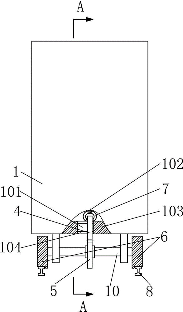
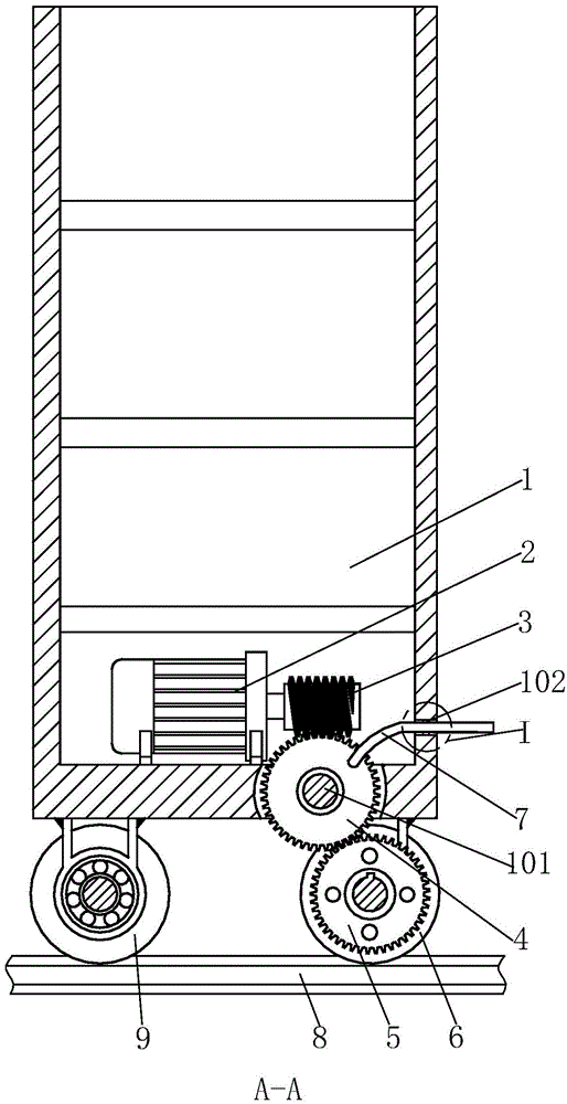
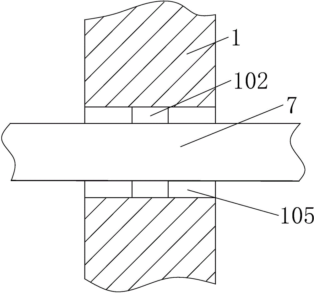
[0020] Such as Figure 1 to Figure 6 As shown, a self-driving tracking toolbox includes a toolbox 1, a motor 2 is fixed at the lower part of the toolbox 1; a worm 3 is installed on the shaft of the motor 2; the bottom of the toolbox 1 is provided The bottom plate 103; the front of the bottom plate 103 is provided with a No. 1 through hole 104; the No. 1 through hole 104 is fixed with a worm gear shaft 101; the worm gear shaft 101 is sleeved with a worm wheel 4 that matches the worm 3; Four wheels are installed on the bottom surface of the bottom plate 103. According to the installation positions of the four wheels, the wheels can be divided into a front wheel 6 and a rear wheel 9, and both are a pair; the front wheel 6 and the rear wheel 9 are b...


PUM


Abstract

The invention relates to a self-driven tool box running on a rail. The self-driven tool box comprises a tool box body, wherein the lower portion of the tool box body is fixedly provided with a motor, a shaft of the motor is provided with a worm, the bottom of the tool box body is provided with a bottom plate, the front of the bottom plate is provided with a first through hole, a worm wheel shaft is fixed in the first through hole, a worm wheel matched with the worm is arranged on the worm wheel shaft in a sleeved mode, the bottom face of the bottom late is provided with a front wheel and a rear wheel, the rail is arranged under the front wheel and the rear wheel, the middle of the front wheel is provided with a wheel shaft, the middle of the wheel shaft is provided with a gear, the gear is meshed with the worm, the lower portion of the front of the tool box body is provided with a second through hole, a vertical shaft is fixed in the second through hole, and a shift fork is arranged on the vertical shaft in a sleeved mode. The tool box has the advantages of being reasonable in structural design, low in cost, convenient to operate and control and the like; by means of control of the on-off state and forward rotation and reverse rotation of the motor, the tool box can be controlled to move, tool boxes at different maintenance places can be conveniently exchanged in use, labor is saved, and the worm wheel and the worm have a self-locking function and can prevent the phenomenon that the tool box rolls abnormally.

Description

Technical field [0001] The invention relates to the technical field of maintenance equipment, in particular to a self-driving tracking toolbox. Background technique [0002] In general maintenance stations or maintenance rooms, there are often multiple maintenance points. Each maintenance point has a maintenance worker responsible for it, and each maintenance worker has his own tools. However, not every maintenance worker has some tools. Yes, such as more expensive tools or tools that are damaged and have not had time to supplement. When maintenance workers need these tools, they need to configure a more comprehensive toolbox to get them. This not only wastes time, wastes manpower, but also affects work efficiency. If the maintenance points are also divided into above-ground maintenance points and underground maintenance warehouses, it will be more troublesome to use tools alternately between these maintenance points. In addition, because the tools are not convenient to put them...

Claims


Application Information

Patent Timeline
Patent Type & Authority Patents(China)
IPC IPC(8): B25H5/00
Inventor 陈祖尧易伟林
Owner HUAQIANG FANGTE WUHU CULTURE TECH CO LTD
Learn More