
Vacuum replenishment system for brake device of motor vehicle in unpowered state

A brake device and motor vehicle technology, applied to brake transmission devices, brakes, vehicle components, etc., can solve the problems of no configuration and achieve the effect of preventing traffic accidents

Inactive Publication Date: 2014-03-19
王水争
View PDF4 Cites 1 Cited by
  • Summary
  • Abstract
  • Description
  • Claims
  • Application Information

AI Technical Summary

Problems solved by technology

Unfortunately, existing motor vehicles are not equipped with such a vacuum replenishment system

Method used


Image

  • Vacuum replenishment system for brake device of motor vehicle in unpowered state

Examples


Embodiment Construction

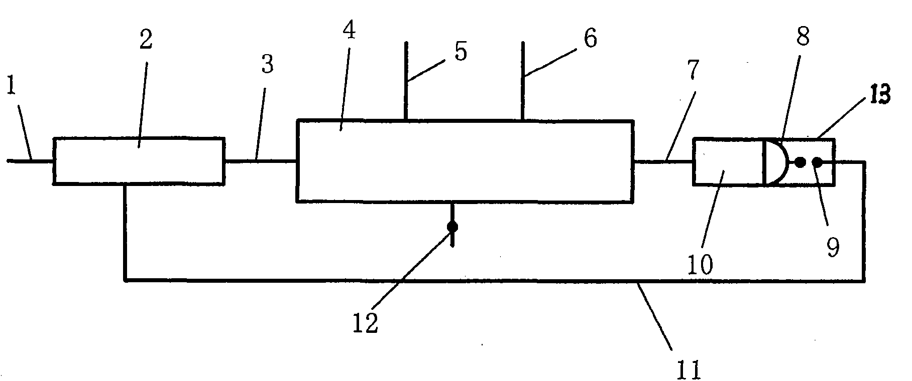
[0011] As shown in the figure, the vacuum supply system for the braking device of the motor vehicle in the unpowered state of the present invention is composed of a vacuum pump 2, an air guide pipe 3, a vacuum tank 4, a vacuum tube 5 connected to the engine, a vacuum tube 6 of the brake device, a connecting air pipe 7, a power cord 11, Air supply valve 12, vacuum monitoring switch 13 composition; It is characterized in that, one end of vacuum pump 2 is provided with exhaust pipe 1, and the other end is provided with air guide pipe 3, and the other end of air guide pipe 3 is connected with one end of vacuum tank 4; Vacuum tank 4 The side of the structure is provided with engine connecting vacuum tube 5 and braking device vacuum tube 6 and air supply valve 12; the other end of vacuum tank 4 is equipped with connecting air pipe 7; connecting air pipe 7 is connected with vacuum monitoring switch 13; one end of vacuum monitoring switch 13 is Vacuum monitoring shell 10, a rubber bowl...


PUM


Abstract

The invention discloses a vacuum replenishment system for a brake device of a motor vehicle in an unpowered state. The vacuum replenishment system consists of a vacuum pump, an air guiding pipe, a vacuum tank, an engine connected vacuum pipe, a brake device vacuum pipe, a connection air pipe, a power cord, a gulp valve and a vacuum monitoring switch. The vacuum replenishment system for the brake device of the motor vehicle in the unpowered state has the benefits as follows: when the motor vehicle is shut down accidentally and is in the unpowered state, the vacuum control for the brake device is restored in time, and failure of a brake function of the brake device is avoided; and accordingly, traffic accidents are reduced or prevented due to the fact that the brake device of the motor vehicle is in a safety state all the time. The vacuum replenishment system can be taken as a pneumatic supply and used for inflating a vehicle tyre.

Description

technical field [0001] The invention relates to the field of motor vehicle braking devices, in particular to a vacuum supply system for the braking device in the non-powered state of the motor vehicle, which is used for the vacuum supply of the braking device system when the motor vehicle is unexpectedly turned off. Background technique [0002] The motor vehicle brake device is composed of three parts: a transmission shaft, a fixed hollow shaft, and a highly elastic sealing rubber ring. Wherein the fixed hollow shaft is sleeved on the transmission shaft, and there is a large gap between the two, and a highly elastic sealing rubber ring is installed in this gap. The inner ring of the rubber ring is always rigidly connected and fixed with the transmission shaft, and the outer ring is inlaid with several friction plates, leaving a certain gap with the surface of the inner diameter of the fixed hollow shaft. When the high-elastic sealing rubber ring is not filled with high-pre...

Claims


Application Information

Patent Timeline
Patent Type & Authority Applications(China)
IPC IPC(8): B60T13/46B60T17/06
Inventor 王水争王云龙王晓培
Owner 王水争
Learn More