Clamping false twisting device

A clamping and false twisting technology, applied in the field of spinning, can solve the problems of high end-breakage rate of false-twisting devices, improve spinning efficiency and yarn production rate, reduce production costs, and reduce spinning end-breakage rate Effect

Active Publication Date: 2016-05-18
GUANGDONG ESQUEL TEXTILES CO LTD +3
View PDF9 Cites 0 Cited by
  • Summary
  • Abstract
  • Description
  • Claims
  • Application Information

AI Technical Summary

Problems solved by technology

[0004] In order to solve the technical problem of the high broken end rate of the existing false twisting device

Method used


Image

  • Clamping false twisting device
  • Clamping false twisting device
  • Clamping false twisting device

Examples


Embodiment 1

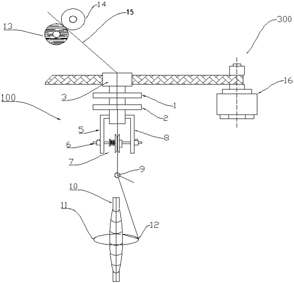
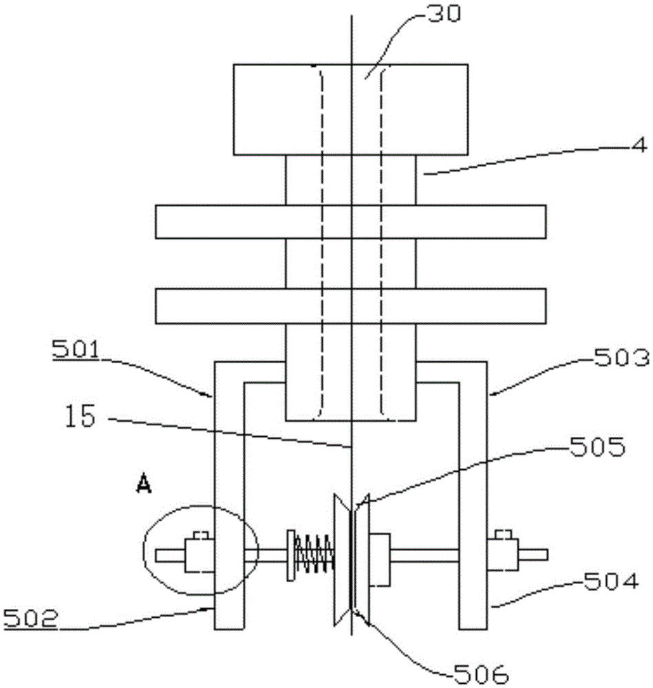
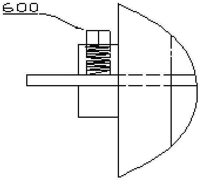
[0027] The clip-type false twisting device of the present invention will be further described in detail below in conjunction with the accompanying drawings. A clamping type false twisting device, comprising a false twist application system 100 and a transmission system 300; the false twist application system 100 includes a rotating disk 3, the rotating disk 3 contains a central hole 30 vertically through, the lower end of the rotating disk 3 A hollow tube 4 is provided, and a false twist clamping mechanism 7 for clamping the yarn 15 is provided below the hollow tube 4; the transmission system 300 includes a motor 16, a transmission belt 202 connecting the motor 16 and the rotating disk 3, such as figure 1 , figure 2 , image 3 and Figure 4 shown.

[0028] The false twist application system 100 is provided with a false twist point and can be adjusted up and down, and the transmission system 300 can be independently controlled. The false twist application system 100 also in...

Embodiment 2

[0039] The clip-type false twisting device of the present invention will be further described in detail below in conjunction with the accompanying drawings. A clamping type false twisting device, comprising a false twist application system 100 and a transmission system 300; the false twist application system 100 includes a rotating disk 3, the rotating disk 3 contains a central hole 30 vertically through, the lower end of the rotating disk 3 A hollow tube 4 is provided, and a false twist clamping mechanism 7 for clamping the yarn 15 is provided under the hollow tube 4;

[0040] In this embodiment, the false twist clamping mechanism 7 includes an upper roller 730 and a lower roller 731 arranged below the hollow tube 4 for clamping the yarn 15, the upper roller 730 and the lower roller 731 are tangent, and the upper roller 730 and the lower roller The tangent point of the roller 731 is the clamping point 736, the hollow tube 4 is connected with the left bracket 733 and the right...

Embodiment 3

[0045] The clip-type false twisting device of the present invention will be further described in detail below in conjunction with the accompanying drawings. A clamping type false twisting device, comprising a false twist application system 100 and a transmission system 300; the false twist application system 100 includes a rotating disk 3, the rotating disk 3 contains a central hole 30 vertically through, the lower end of the rotating disk 3 A hollow tube 4 is provided, and a false twist clamping mechanism 7 for clamping the yarn 15 is provided under the hollow tube 4;

[0046] The false twist clamping mechanism 7 includes a left yarn clamping block 720 and a right yarn clamping block 721 arranged below the hollow tube 4, the left yarn clamping block 720 and the right yarn clamping block 721 are connected by a cross bar 723, and the left yarn clamping block 720 can Slide left and right on the crossbar 723, the part where the left yarn clamping block 720 and the right yarn clam...


PUM

PropertyMeasurementUnit
surface roughnessaaaaaaaaaa

Abstract

The invention provides a clamping false twisting device which comprises a false twisting exerting system (100) and a transmission system (300). The false twisting exerting system (100) comprises a rotation disc (3), a through center hole along the vertical direction is formed in the rotation disc (3), a hollow pipe (4) is arranged at the lower end of the rotation disc (3), and a false twisting clamping mechanism (7) for clamping yarn (15) is arranged below the hollow pipe (4). The false twisting device is applicable to middle-low-count yarn and high-count yarn, such as 200S even 300S yarn, can effectively reduce spinning breakage of high-count yarn or even ultra-high-count yarn, improves spinning efficiency and yarn pull rate and remarkably reduces production cost. The device is simple and convenient to operate, can be obtained by modifying the existing spinning frame, is low in modifying cost, can effectively increase the additional value of the existing spinning frame and is in accordance with the sustainable development requirements.

Description

technical field [0001] The invention relates to the technical field of spinning, in particular to a clamping type false twisting device. Background technique [0002] Twisting is an important part of short fiber spinning. At present, ring spinning is still the most widely used spinning technology at home and abroad. Ring spinning consists of a steel traveler, a steel ring and a high-speed rotating spindle. The air circle and winding form will produce spinning tension and tension fluctuations. Excessive spinning tension and tension fluctuations will cause an increase in the yarn breakage rate, which limits the increase in spindle speed and output. In recent years, through the unremitting efforts of textile workers, a method and device for false twist assisted spinning to reduce yarn breakage in spinning have been proposed. There are six forms in summary. The first is air-flow rotating false twist, and the second is mechanical spinning. Center rotating false twisting, the thi...

Claims


Application Information

Patent Timeline
Patent Type & Authority Patents(China)
IPC IPC(8): D01H7/92D01H1/241
Inventor 何小东刘霞刘伟伟宋均燕张玉高赵阳李刚贾文杰罗国
Owner GUANGDONG ESQUEL TEXTILES CO LTD
Why Eureka
Try Eureka