
Backlight module

A backlight module and light source technology, applied in optics, light guides, light sources, etc., can solve the problem of easy gaps between the light source and the light guide plate, and achieve the effect of ensuring optical quality

Inactive Publication Date: 2016-04-06
AU OPTRONICS CORP
View PDF6 Cites 0 Cited by
  • Summary
  • Abstract
  • Description
  • Claims
  • Application Information

AI Technical Summary

Problems solved by technology

[0005] In view of the deficiencies in the prior art, the purpose of the present invention is to propose a backlight module, in order to solve the problem that a gap is easily generated between the light source and the light guide plate in the side-light backlight module

Method used


Image

  • Backlight module
  • Backlight module
  • Backlight module

Examples


Embodiment Construction

[0051] The technical solution of the present invention will be described in detail below in conjunction with the accompanying drawings and specific embodiments to further understand the purpose, solution and effect of the present invention, but it is not intended to limit the scope of protection of the appended claims of the present invention.

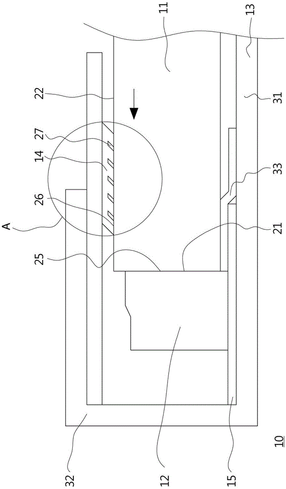
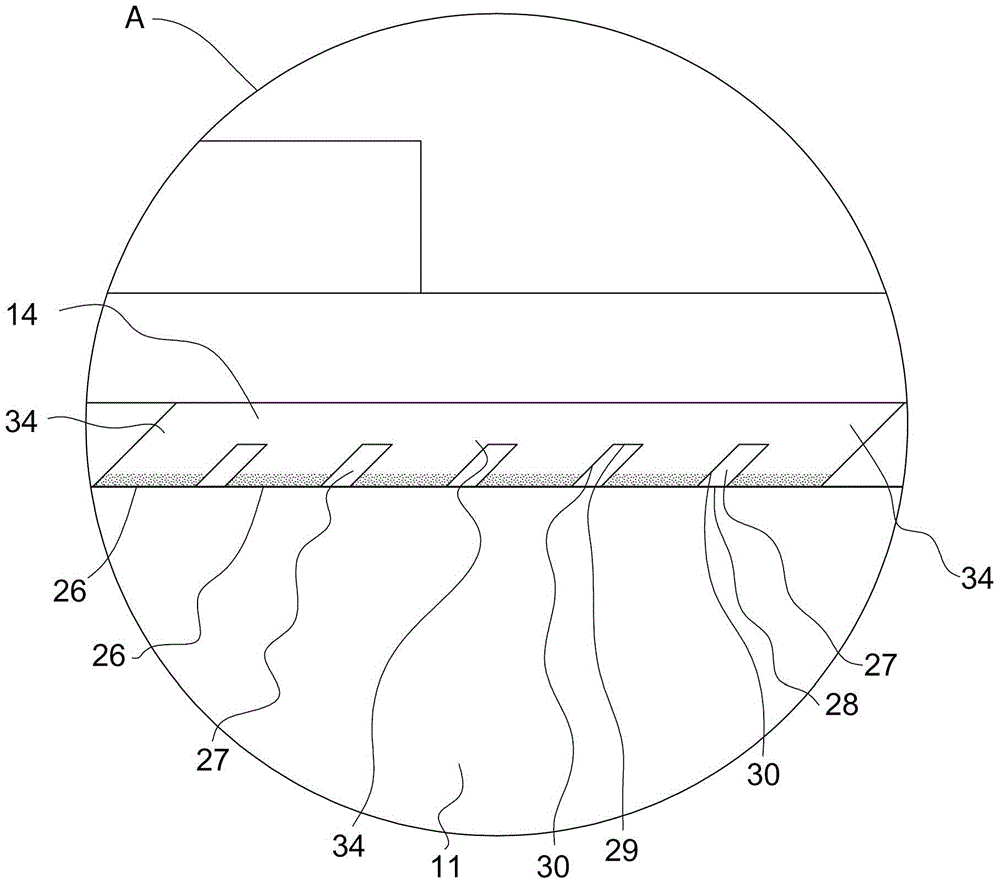
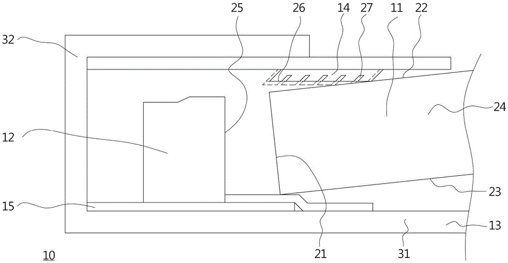
[0052] Figure 1-1 to Figure 1-5 Shown is a partial cross-sectional schematic diagram of a backlight module according to an embodiment of the present invention, Picture 1-1 The picture shows how the light guide plate has been positioned. Figure 1-2 for Picture 1-1 Partial enlargement of area A of , to highlight the detailed structure of the resistance part, which mainly shows the structure of the resistance part, Figure 1-3 The process shown is the insertion of the light guide plate into the frame, Figure 1-4 Shown is the matching relationship between the light guide plate and the resistance member, Figure 1-5 for Figure 1-4 ...


PUM


Abstract

The invention relates to a backlight module applicable to a display device. The backlight module comprises a light guide plate, a light source, a frame and a resistance part. The light guide plate comprises an incident light face. The light source is arranged facing the incident light face. The light source and the light guide plate are located in the frame. The resistance part is clamped between the light guide plate and the frame, and is adjacent to the light source. The resistance part includes a resistance face and a taper slot. The resistance face is in contact with the light guide plate. The taper slot has two inner walls adjoined to the resistance face and extending in a tilt direction departing from the incident light face and far away from the resistance face, wherein the tilt direction is not perpendicular to the normal direction of the incident light face. Compared with the prior art, the optical quality of the backlight module provided by the invention is ensured.

Description

technical field [0001] The present invention relates to a backlight module; in particular, it relates to an edge-lit backlight module in which the light source is arranged on the side of the light guide plate. Background technique [0002] All existing liquid crystal display devices need to be equipped with a backlight module, and the backlight module is used to generate a surface light source. The light generated by the surface light source enters from one side of the liquid crystal panel, and through the action of liquid crystal molecules, color filters and other related components, presents an image on the display side of the liquid crystal panel. Among them, the optical quality of the surface light source produced by the backlight module, including luminance, light uniformity, etc., has a significant and direct impact on the image presented by the liquid crystal panel. [0003] Existing backlight modules are mainly divided into two types, one is a direct-type backlight ...

Claims


Application Information

Patent Timeline
Patent Type & Authority Patents(China)
IPC IPC(8): G02F1/13357F21V8/00F21Y115/10
Inventor 杜玮珊黄启祥陈建州林士斌
Owner AU OPTRONICS CORP
Learn More