Optical lens, lens barrel and air cooling structure

A technology of optical mirrors and lens barrels, applied in the field of optical systems, can solve problems such as complex design, low efficiency, and high technical difficulty

Active Publication Date: 2021-05-07
四川中科朗星光电科技有限公司
View PDF21 Cites 0 Cited by
  • Summary
  • Abstract
  • Description
  • Claims
  • Application Information

AI Technical Summary

Problems solved by technology

The cooling efficiency of the device for water-cooling the mirror base is not high
[0006] To sum up, for the negative lens phenomenon caused by the heating of gas, the existing technology has problems such as complex design, high technical difficulty, and low efficiency.

Method used


Image

  • Optical lens, lens barrel and air cooling structure
  • Optical lens, lens barrel and air cooling structure
  • Optical lens, lens barrel and air cooling structure

Examples


Embodiment 1

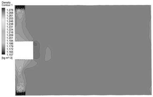
[0041] In this embodiment, the diameter of the optical mirror body 1 is 1m, and the heat of the optical mirror body 1 after absorbing the heat of the laser is 50 W / ㎡; the length of the lens barrel 2 is 1.5 m; the gas in the lens barrel 2 is air, and the ambient pressure is not less than 1 atm .

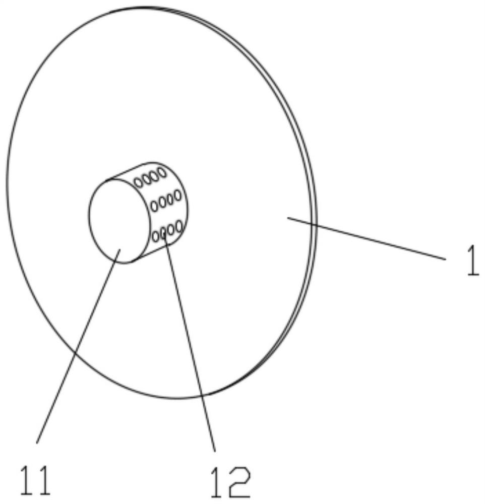
[0042] The axial distribution range of the second air holes 21 on the wall of the lens barrel 2 is 0.1m, the diameter of the second air holes 21 is 0.01m, and there are 10 rows evenly distributed on the circumference, 4-5 in each row, and the hole distance of each row is 0.02m . The diameter of the first ventilation holes 12 is 0.01m, the hole pitch is 0.02m, and the axial distribution range is 0.1m.

[0043] When working, the intake gas is pure nitrogen, and the intake velocity V 进气 =0.1m / s, pumping speed V 抽气 =V 进气 .

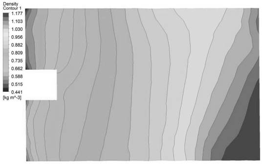
[0044] Such as Figure 5 As shown, the density in the lens barrel 2 of the prior art is distributed in the range of 0.441-1.177 kg / m³, and the gas density near ...


PUM


Abstract

The invention relates to an optical lens, a lens barrel and an air cooling structure, the air cooling structure comprises the lens barrel and the optical lens, the side wall of one end of the lens barrel is provided with a plurality of second vent holes, and the optical lens is installed at the end, provided with the second vent holes, of the lens barrel; a ventilation opening is formed in the center of the optical lens, a hollow convex part is arranged at the ventilation opening, one end of the hollow convex part is open, the open end of the hollow convex part is connected with the edge of the ventilation opening, and a plurality of first ventilation holes are formed in the hollow convex part. The mirror surface and surrounding environment gas can be cooled, the efficiency is high, and the effect is good; the air cooling structure can cool the mirror surface and surrounding environment gas, and is high in efficiency and good in effect; when the high-power optical system works, heat of the optical lens and surrounding air can be dissipated in real time, the phenomenon that the optical lens absorbs heat to cause the negative lens phenomenon of environment gas is avoided, and the optical quality of transmitted light is guaranteed.

Description

technical field [0001] The invention relates to the technical field of optical systems, in particular to an optical mirror, a lens barrel and an air cooling structure. Background technique [0002] When the power of the transmitted light in the optical system is too high, after the optical mirror absorbs heat, the absorbed heat will heat the surrounding air, causing the air pressure to rise, the air to expand, the air density to decrease, and the refractive index to decrease, forming a negative lens to diverge the beam. It seriously affects the quality of beam transmission and is one of the most serious problems encountered in laser transmission. At present, two commonly used improvement methods are adaptive optics technology and water cooling technology. [0003] For example, the Chinese patent document with the application number 201910972475.X discloses a simulation device for the thermal halo effect of laser transmission and its adaptive optical compensation. The techn...

Claims


Application Information

Patent Timeline
Patent Type & Authority Applications(China)
IPC IPC(8): G02B7/02
CPCG02B7/028
Inventor 杨博宋伟红
Owner 四川中科朗星光电科技有限公司
Why Eureka
Try Eureka