Air conditioner for vehicle capable of immediately cooling vehicle compartment

a technology for air conditioners and vehicles, applied in vehicle components, vehicle heating/cooling devices, railway heating/cooling, etc., can solve the problems of increased cost, large heat loss in air distribution ducts after evaporation, high temperature of sucked air, etc., and achieve the effect of improving the capability of immediately cooling passangers and low cos

Inactive Publication Date: 2006-06-08
DENSO CORP
View PDF3 Cites 12 Cited by
  • Summary
  • Abstract
  • Description
  • Claims
  • Application Information

AI Technical Summary

Benefits of technology

[0010] The above-mentioned conventional problems being taken into account, the present invention has been developed, although cooling is focused on, and the object thereof is to provide an air conditioner for a vehicle capable of improving the capability for immediately cooling passangers at a low cost.

Problems solved by technology

However, conventionally, it usually takes a few minutes to obtain air cold enough to cause a passenger to feel comfortable.
Besides the problem of the cooling capacity of the air conditioner, the biggest problems are that (1) the temperature of the sucked air is high and that (2) the heat losses in air distribution ducts after an evaporator are large.
However, the technique in the above-mentioned patent document 1 is insufficient as a countermeasure against the problem that (1) the temperature of sucked air is high because air discharged from the air leakage port diffuses from a part deep in an instrument panel so that the structure is not necessarily one in which all the air is sucked by the blower from the air leakage port.
Further, as a countermeasure against the problem that (2) the heat losses in the air distribution ducts after the evaporator are large, it is insufficient because air discharged from the evaporator flows through an air conditioning unit and an already existing vehicle air distribution duct, thereby receiving heat and, therefore, the temperature of the air rises before it is sucked by the blower.
Furthermore, there is another problem that the cost is increased because of the need to provide a space for an open / close door to be provided in the air distribution duct, and due to the cost of the door and a drive mechanism.

Method used


Image

  • Air conditioner for vehicle capable of immediately cooling vehicle compartment
  • Air conditioner for vehicle capable of immediately cooling vehicle compartment
  • Air conditioner for vehicle capable of immediately cooling vehicle compartment

Examples


Embodiment Construction

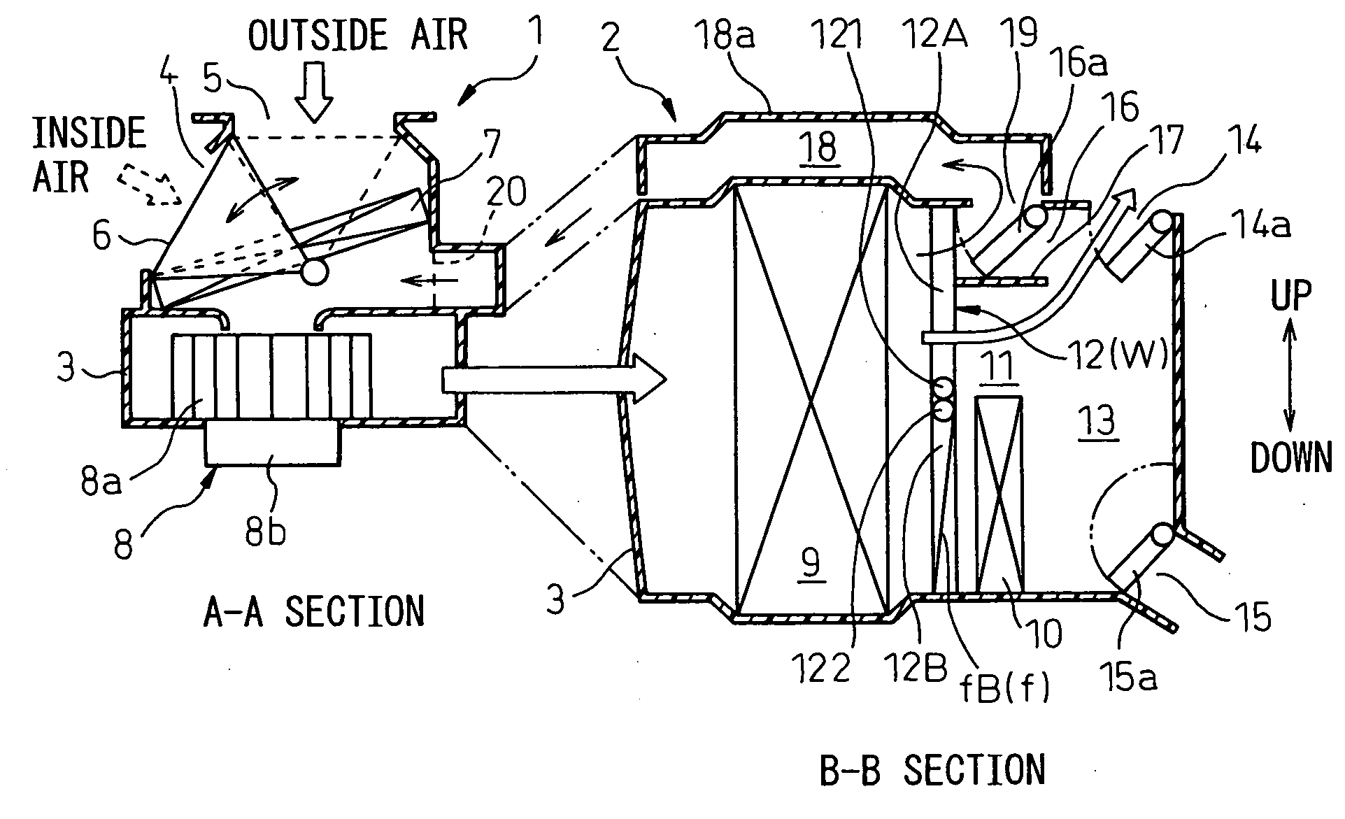
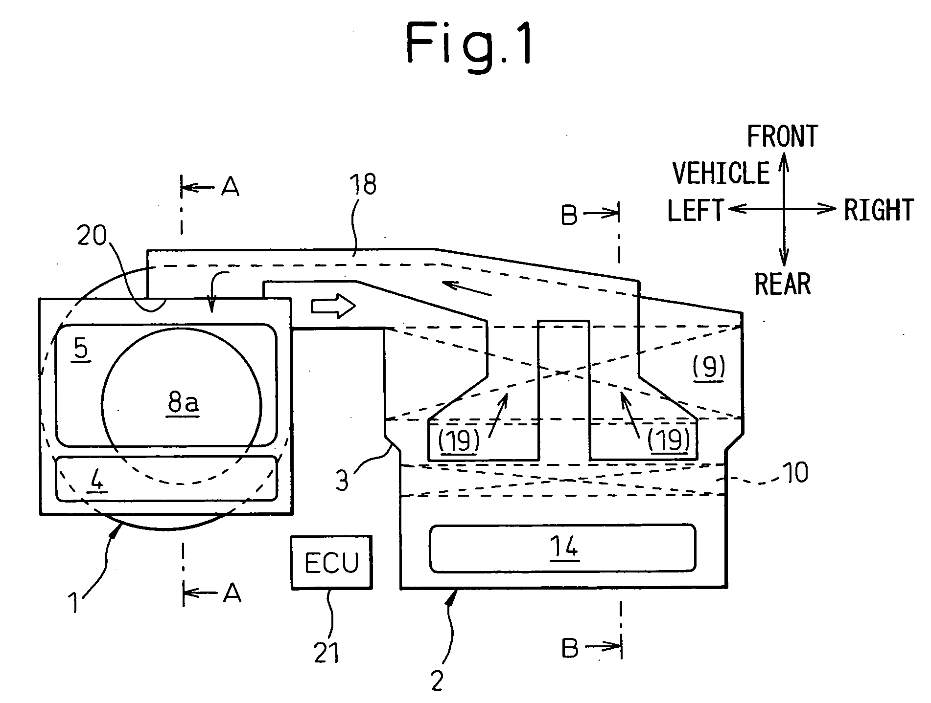
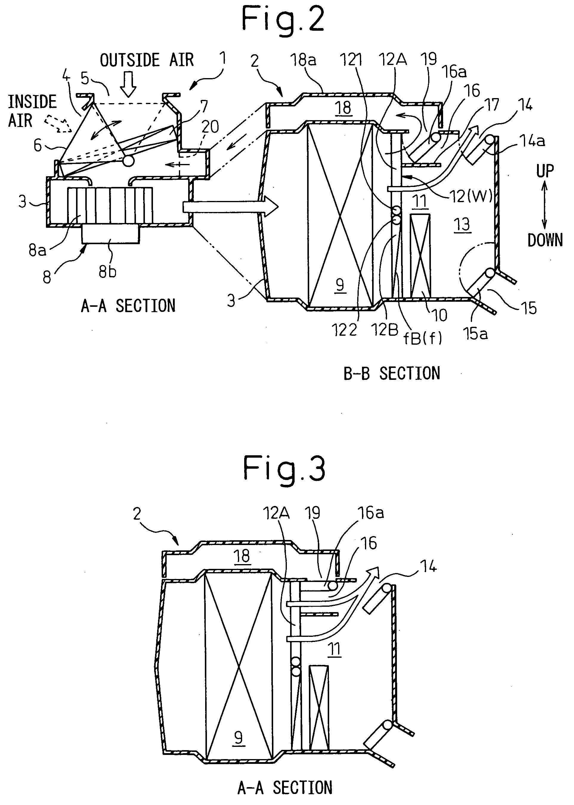
[0022] Embodiments of the present invention are explained below in detail using drawings. FIG. 1 is a top view of an air conditioner for a vehicle in an embodiment of the present invention. FIG. 2 is a diagram showing A-A section view of an air supply unit 1 and B-B section view of an air conditioning unit 2 in FIG. 1 side by side, also showing a state in which an air introduction inlet 19 leading to a short circuit duct 18 is opened by a cold air bypass door 16a. In the explained embodiment, the present invention is applied to an air conditioner for a vehicle that is installed at the front seat of a vehicle in which a water-cooled engine is installed.

[0023] The ventilation system of the air conditioner for a vehicle according to the present embodiment can be roughly divided into two sections, that is, the air supply unit (air supply section) 1 and the air conditioning unit (air conditioning section) 2. The air supply unit 1 is arranged at a position offset from the center toward t...


PUM


Abstract

A short circuit duct 18, which branches at least part of air flowing through a cold air bypass passage 16 and causes a fan to suck it, is provided. According to this, part of cold air is taken out at a position as close as possible after an evaporator and is circulated again through a route as short as possible, whereby the discharged air temperature is further reduced. A low discharged air temperature can be attained quickly by efficiently returning the cold air immediately after the evaporator to the fan through the shortest route, which can be realized by providing an air introduction inlet 19 directly to an air conditioning case on the top surface of the existing cold air bypass passage 16 immediately after the evaporator 9 and using the short circuit duct 18 with small heat capacity after the air introduction inlet.

Description

BACKGROUND OF THE INVENTION [0001] 1. Field of the Invention [0002] The present invention relates to an air conditioner, for a vehicle, mounted on a vehicle such as an automobile to perform cooling, heating, etc. More particularly, it relates to an air conditioner for a vehicle comprising a cold air bypass passage for directly guiding air having passed through an evaporator to a face opening while causing the air to bypass a heater core and an air mix section. [0003] 2. Description of the Related Art [0004] Recently, there is an increasing demand to obtain cold air as soon as possible at the time of cool-down of a vehicle compartment immediately after boarding. However, conventionally, it usually takes a few minutes to obtain air cold enough to cause a passenger to feel comfortable. Besides the problem of the cooling capacity of the air conditioner, the biggest problems are that (1) the temperature of the sucked air is high and that (2) the heat losses in air distribution ducts afte...

Claims


Application Information

Patent Timeline
Patent Type & Authority Applications(United States)
IPC IPC(8): B60H3/00B60H1/00B61D27/00
CPCB60H1/00035B60H2001/00085B60H2001/00164
Inventor MURAKI, TOSHIHIKO
Owner DENSO CORP
Why Eureka
Try Eureka