lens

A lens and optical axis technology, applied in the direction of lenses, instruments, optics, etc., can solve the problems of poor imaging quality and influence of lenses, achieve the effect of ensuring optical quality and reducing the chance of joint lines

Active Publication Date: 2021-04-30
YOUNG OPTICS
View PDF5 Cites 0 Cited by
  • Summary
  • Abstract
  • Description
  • Claims
  • Application Information

AI Technical Summary

Problems solved by technology

When this combination line extends into the effective refractive zone of the lens, it will have a negative impact on the imaging quality of the lens.

Method used


Image

  • lens
  • lens
  • lens

Examples


Embodiment Construction

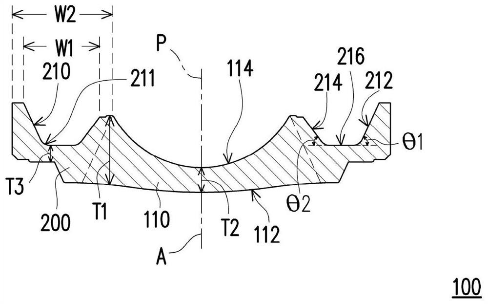
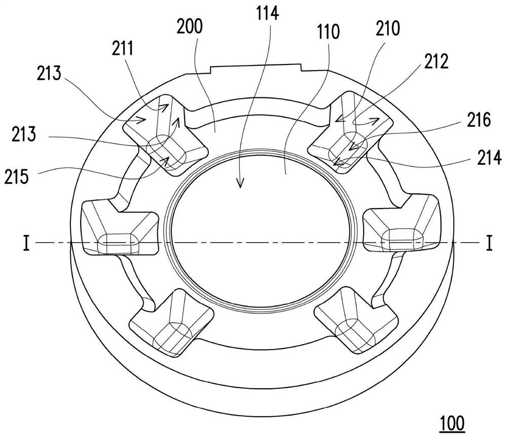
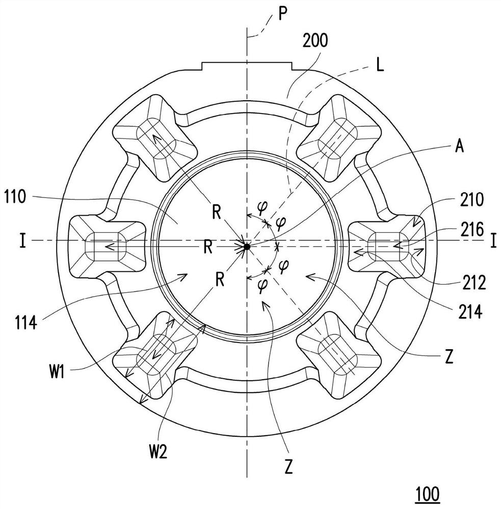
[0050] Figure 1A It is a schematic cross-sectional view of a lens according to an embodiment of the present invention, Figure 1B for Figure 1A The three-dimensional schematic diagram of the lens, and Figure 1C for Figure 1A The schematic diagram of the top view of the lens, where Figure 1A The profile is along the Figure 1B and Figure 1C The profile of the I-I line. Please refer to Figure 1A to Figure 1C , the lens 100 of this embodiment includes a diopter 110 and an edge 200 . The diopter 110 has a negative diopter, so that light rays passing through the diopter 110 are more deflected toward the direction of divergence. The edge portion 200 surrounds the refraction portion 110 and is located outside the effective refraction zone of the lens 100 . The effective refractive area means that when the light passes through this area, it can be effectively focused or astigmatized by the curved surface of the lens 100 (such as the first surface 112 and the second surface...


PUM


Abstract

The invention relates to a lens, which includes a refractive part and an edge part. The diopter has a negative diopter, and the edge surrounds the diopter and is located outside the effective diopter area of ​​the lens. The edge portion has a plurality of depressions which are arranged mirror-symmetrically with respect to a plane of symmetry containing the optical axis of the lens. The maximum thickness ratio of the lens is greater than 2.5. When the fluid is injected from the gate into the mold cavity, the wavefront of the fluid can reach the opposite side of the gate more evenly, and will not collide before reaching the opposite side of the gate, so as to reduce the combination of the refractive part in the lens The opportunity of the line, whereby the optical quality of the lens can be ensured.

Description

technical field [0001] The present invention relates to an optical element, and in particular to a lens with a plurality of concave structures on its surface. Background technique [0002] The lens is a basic and indispensable optical element in the optical system, and it plays an extremely critical and important role in the optical imaging lens. The imaging quality of an optical imaging lens is directly related to the quality of the lens it uses, so how to manufacture a lens with good quality has become one of the important issues in manufacturing an optical system. [0003] In order to cope with the continuous improvement of the performance requirements of today's optical imaging lenses, it is necessary to use a lens with a large thickness ratio in the lens, which can be understood as the ratio of the maximum thickness to the minimum thickness of the lens in the direction parallel to the optical axis is relatively large. However, when the injection molding process is used...

Claims


Application Information

Patent Timeline
Patent Type & Authority Patents(China)
IPC IPC(8): G02B3/02
CPCG02B3/02
Inventor 颜振宇施耀竣蔡明昌
Owner YOUNG OPTICS
Why Eureka
Try Eureka