Vehicle roof structure and vehicle

A vehicle roof and canopy technology, which is applied in the direction of freight vehicles, motor vehicles, load coverage, etc., can solve the problems of distortion, large deformation, and uneven stress on the roof, and achieve the requirements of reducing rigidity and reducing Position requirements, the effect of reducing vehicle weight

Active Publication Date: 2014-03-26
CIMC VEHICLES (GROUP) CO LTD +1
View PDF8 Cites 2 Cited by
  • Summary
  • Abstract
  • Description
  • Claims
  • Application Information

AI Technical Summary

Problems solved by technology

For the soft tarpaulin system, it is generally covered manually or with a rope, but the operation of this soft tarpaulin system is time-consuming and laborious, and the efficiency is low
For the rigid top cover, the top cover is forcibly opened by the power structure (such as hydraulic cylinder or pneumatic cylinder). However, in the process of forcibly opening the power structure, the top cover is prone to uneven force, resulting in local distortion and deformation. Especially for self-unloading vehicles, due to the different structures of the front and rear parts, the lifting power can only be provided by the power system at the front of the vehicle, resulting in a large amount of deformation during the movement of the roof, and the structure is easily damaged
In order to overcome this problem, it is necessary to increase the rigidity of the frame, which increases the cost of the canopy and requires a greater opening force, which has higher requirements for the power system

Method used


Image

  • Vehicle roof structure and vehicle
  • Vehicle roof structure and vehicle
  • Vehicle roof structure and vehicle

Examples


Embodiment 1

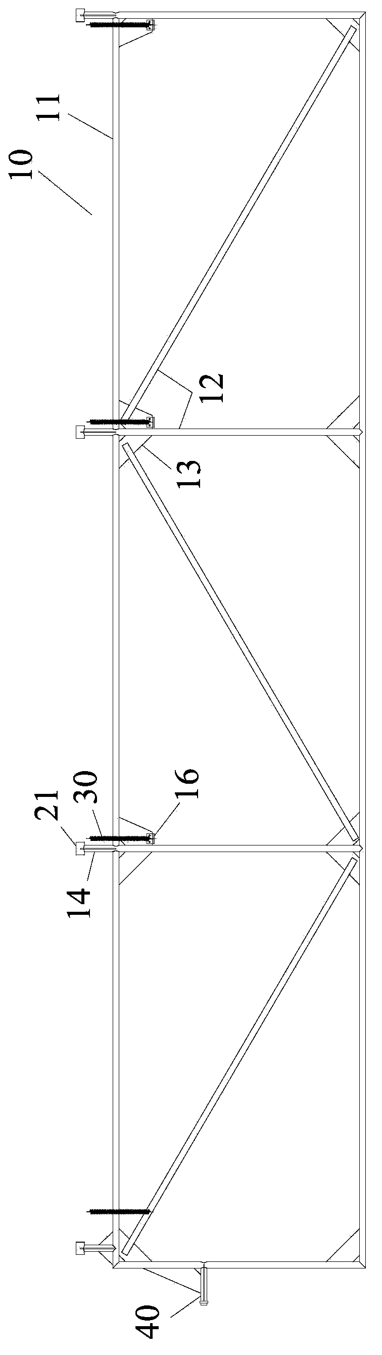
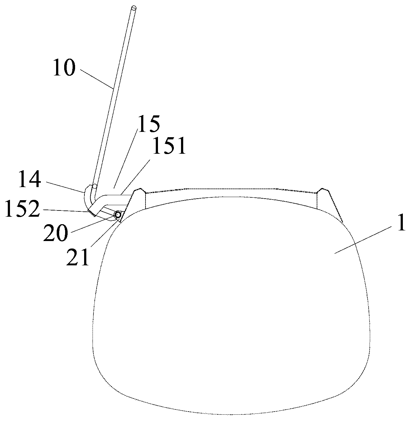
[0027] like figure 1 , 2 As shown, the roof structure of this embodiment includes a roof 10, a rotating shaft 20 and elastic elements. The canopy 10 covers the opening at the top of the box body 1 and is rotatably mounted on one side of the box body 1 through a rotating shaft 20 . The canopy 10 turns around the box body 1 to cover or open the opening. The roof 10 includes a roof frame surrounded by four frames 11 and a plurality of roof rods 12 whose two ends are respectively connected to the roof frame, and a plurality of ribs 13 fixedly connected to the ends of the roof rods 12 and the roof frame . A plurality of canopy rods 12 are arranged in the four frames 11 in a certain layout, so as to support the upper cloth or net (not shown) to form a canopy and cover the top of the box body 1 . The ribs 13 can connect the canopy pole 12 and the adjacent frame 11 to improve the strength of the canopy. The canopy 10 is similar to the prior art, so it will not be repeated here.

...

Embodiment 2

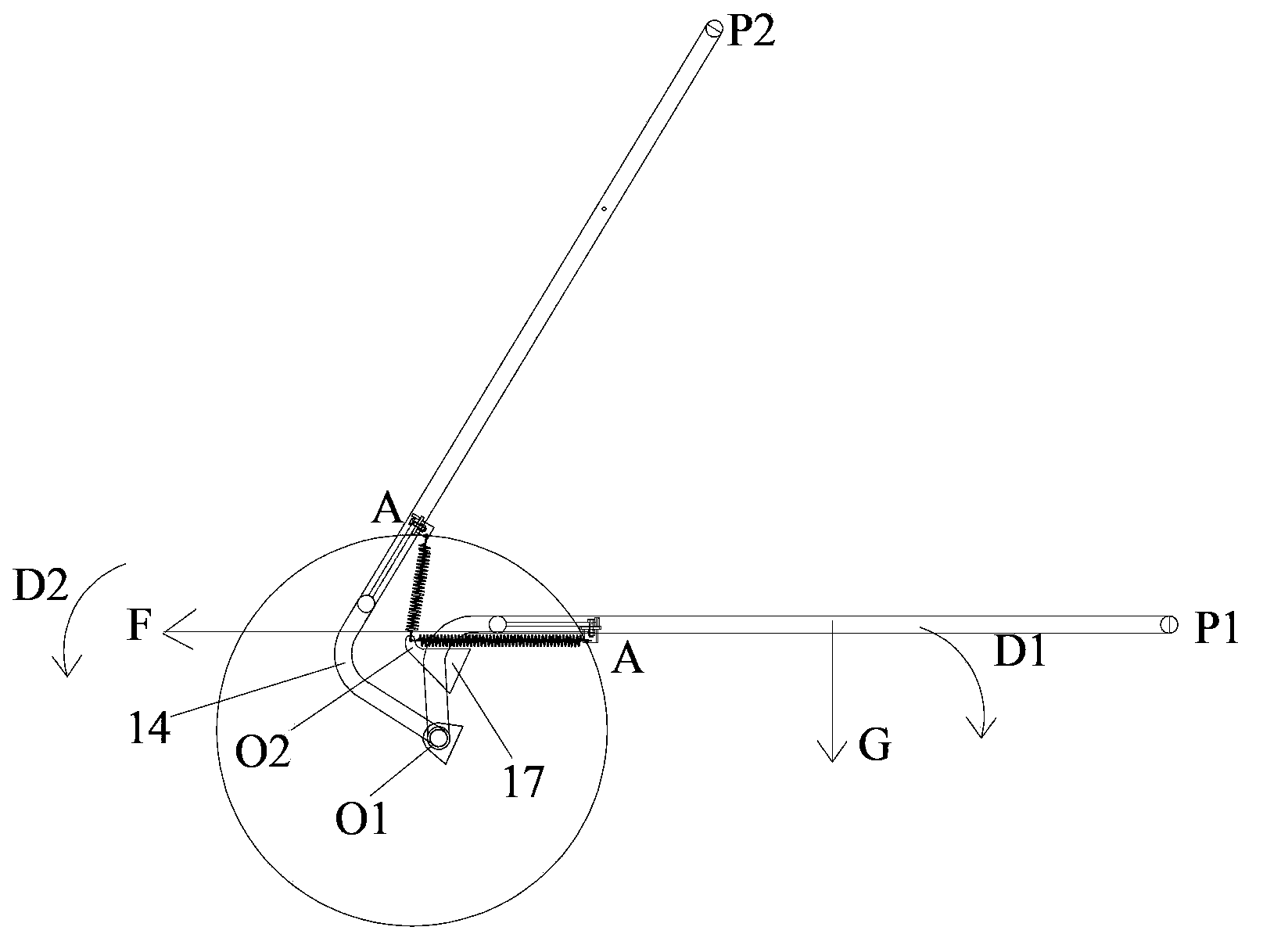
[0035] like Figure 4 As shown, the telescopic spring is a compression spring, the second mounting seat 17 is located on one side of the top of the box body, and the second mounting hole is located below the rotating shaft 22 . In the closed state, the compression spring 30 is in a compressed state with a certain amount of compression. At this time, the direction of the moment generated by the compression spring 30 is D2 (counterclockwise), and the direction of the moment D1 (clockwise) generated by the gravity of the canopy, that is, the directions of the two moments are opposite, so that the canopy is opened with less effort. In the fully opened state of the roof, the compression spring 30 is in a free state or in a compressed state, and the compression amount at this time is 0, or less than that in the compressed state. During the entire overturning process, the direction of the moment generated by the compression spring 30 is always opposite to the direction of the moment...


PUM


Abstract

The invention provides a vehicle roof structure and a vehicle. The vehicle roof structure is used for covering the opening of the top of a vehicle box. The vehicle roof structure comprises a roof installed on one side of the box in a rotating mode through a rotating shaft. The roof rotates around the box to cover or open the opening. The vehicle roof structure further comprises at least one elastic element. One end of the elastic element is fixed to the roof, and the other end of the elastic element is fixed to the box. When the roof turns over, torque generated by the elastic element can offset part of torque generated by the gravity of the roof.

Description

technical field [0001] The invention relates to a vehicle roof structure and a vehicle, in particular to a vehicle roof structure and a vehicle with the energy-saving roof opening. Background technique [0002] In road transport vehicles, for vehicles with open tops, in order to prevent the loaded goods from floating and flying during driving, these vehicles often install roof structures on the boxes to prevent these problems from occurring. [0003] At present, the roof structure installed on some vehicles is generally a soft tarpaulin or a rigid roof. For the soft tarpaulin system, it is generally covered manually or by using ropes, but the operation of this soft tarpaulin system is time-consuming and laborious, and its efficacy is low. For the rigid top cover, the top cover is forcibly opened by the power structure (such as hydraulic cylinder or pneumatic cylinder). However, in the process of forcibly opening the power structure, the top cover is prone to uneven force, r...

Claims


Application Information

Patent Timeline
Patent Type & Authority Applications(China)
IPC IPC(8): B60P7/02
Inventor 严明刘浪王刘燕
Owner CIMC VEHICLES (GROUP) CO LTD
Why Eureka
Try Eureka