Grille lamp

A grille light and grille technology, applied in the field of grille lights, can solve the problems of increasing the danger of grille lights, complicated structure of lamps, etc.

Inactive Publication Date: 2014-03-26
CHANGZHOU CITY PINGGANG MACHINERY
0 Cites 0 Cited by

AI-Extracted Technical Summary

Problems solved by technology

[0002] The design of modern grille lights is more and more beautiful, but due to the complex structure of the lamps, it is very troublesome to clean the grille lights. It usually takes a lot of effort to disassemble the lamps and then clean them, which brings great inconv...

Method used

The working principle of the present invention is that the cleaning wipe head 9 is threaded with the cleaning push block 8, and then the cleaning push block 8 is installed on the slide rail 7 provided in the chute 6 at both e...

Abstract

The invention discloses a grille lamp. The grille lamp comprises a grille lamp body, a reflector set, a grille assembly and a cleaning device. The reflector set is installed on the inner side of the grille lamp body, the grille assembly is installed on the outer side of the grille lamp body, a lamp tube is installed between the reflector set and the grille assembly, the two ends of the reflector set are provided with sliding grooves, sliding rails are arranged inside the sliding grooves, the cleaning device comprises a cleaning pushing block and a cleaning wiping head, the two ends of the cleaning pushing block are in sliding connection with the sliding rails, and the cleaning wiping head is installed on the cleaning pushing block. By means of the method, the grille lamp can be conveniently and easily cleaned in daily life, the cleaning pushing block is pushed to drive the cleaning wiping head connected to the cleaning pushing block to easily and practically clean the reflector set, dismounting is not needed, and the process is safe and convenient.

Application Domain

Lighting elementsFixed installation

Technology Topic

EngineeringMechanical engineering

Image

  • Grille lamp
  • Grille lamp

Examples

  • Experimental program(1)

Example Embodiment

[0016] The technical solutions in the embodiments of the present invention will be clearly and completely described below. Obviously, the described embodiments are only a part of the embodiments of the present invention, rather than all the embodiments. Based on the embodiments of the present invention, all other embodiments obtained by those of ordinary skill in the art without creative efforts shall fall within the protection scope of the present invention.
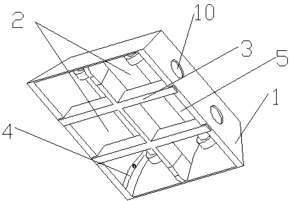
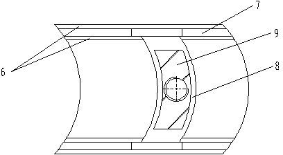
[0017] see figure 1 and figure 2 , the embodiments of the present invention include:
[0018] A grille lamp, comprising: a grille lamp body 1, a reflective sheet group 2, a grille assembly 3 and a cleaning device 4, the reflective sheet group 2 is installed on the inner side of the grille lamp body 1, and the grille assembly 3 is installed on the outside of the grille lamp body 1, the lamp tube 5 is installed between the reflective sheet group 2 and the grille assembly 3, the two ends of the reflective sheet group 2 are provided with chute 6, the chute 6. A slide rail 7 is provided inside, and the cleaning device 4 includes a cleaning push block 8 and a cleaning wiper 9. Both ends of the cleaning push block 8 are slidably connected to the slide rail 7. Clean the wiper head 9 as described above.
[0019] In addition, both the reflective sheet group 2 and the grille assembly 3 are made of flame retardant materials.
[0020] In addition, the reflective sheet group 2 is in a deep arc shape.
[0021] In addition, the cleaning push block 8 does not have a deep arc corresponding to the reflector set 2 .
[0022] In addition, the cleaning wiper head 9 is screwed with the cleaning push block 8 .
[0023] In addition, at least two corresponding heat dissipation holes 10 are opened on both sides of the grille lamp body 1 .
[0024] In addition, the reflective sheet group 2 and the grille assembly 3 are respectively placed in parallel with the grille lamp body 1 .
[0025] The working principle of the present invention is that the cleaning wiper head 9 is screwed with the cleaning push block 8, and then the cleaning push block 8 is installed on the slide rails 7 in the sliding grooves 6 at both ends of the reflective sheet, and only the cleaning push block 8 needs to be pushed. , the cleaning of the reflective sheet group 2 can be completed without disassembling the grille assembly 3 and the lamp tube 5, which is safe and convenient.
[0026] The above descriptions are only the embodiments of the present invention, and are not intended to limit the scope of the present invention. Any equivalent structure or equivalent process transformation made by using the contents of the description of the present invention, or directly or indirectly applied in other related technical fields, will be Similarly, it is included in the scope of patent protection of the present invention.

PUM

no PUM

Description & Claims & Application Information

We can also present the details of the Description, Claims and Application information to help users get a comprehensive understanding of the technical details of the patent, such as background art, summary of invention, brief description of drawings, description of embodiments, and other original content. On the other hand, users can also determine the specific scope of protection of the technology through the list of claims; as well as understand the changes in the life cycle of the technology with the presentation of the patent timeline. Login to view more.
Why Eureka
Try Eureka