Heat accumulation type burner used for industrial production
A technology of regenerative type and regenerator, which is applied in the direction of burners, combustion methods, combustion types, etc., can solve the problems of low efficiency and limited heat stored in regenerators, and achieve improved heat storage efficiency, high heat storage efficiency, Effect of improving ability to absorb heat
- Summary
- Abstract
- Description
- Claims
- Application Information
AI Technical Summary
Problems solved by technology
Method used
Image

Examples
Embodiment Construction
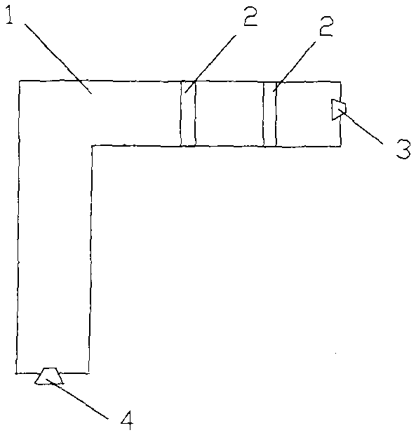
[0012] The technical solution of the present invention will be described in detail below in conjunction with the accompanying drawings.
[0013] Such as figure 1 As shown, a regenerative burner for industrial production according to the present invention includes an inverted L-shaped shell 1, a regenerator 2, a gas burner 3 and an air burner 4. The casing 1 includes a horizontal pipe and a vertical pipe located below the horizontal pipe, and one end of the horizontal pipe is sealingly connected with one end of the vertical pipe. The gas burner 3 is arranged at the other end of the horizontal pipe, the air burner 4 is arranged at the bottom of the vertical pipe, and the regenerator 2 is fixedly connected in the inner cavity of the horizontal pipe.
[0014] In the regenerative burner with the above structure, the air introduced into the air burner 4 brings the heat stored on the regenerator 2 to the furnace, and the gas burner 3 ejects gas, and the air provides heat for the com...
PUM
 Abstract
Description
Claims
Application Information
 - Generate Ideas
- Intellectual Property
- Life Sciences
- Materials
- Tech Scout
- Unparalleled Data Quality
- Higher Quality Content
- 60% Fewer Hallucinations
Browse by: Latest US Patents, China's latest patents, Technical Efficacy Thesaurus, Application Domain, Technology Topic, Popular Technical Reports.
© 2025 PatSnap. All rights reserved.Legal|Privacy policy|Modern Slavery Act Transparency Statement|Sitemap|About US| Contact US: help@patsnap.com