
Carbon dioxide heat pump system and control method thereof

A technology of heat pump system and carbon dioxide, applied in heat pumps, refrigerators, refrigeration components, etc., to achieve the effect of fast hot water production and energy saving

Active Publication Date: 2016-05-11
JIANGSU SUJING GROUP +1
View PDF9 Cites 0 Cited by
  • Summary
  • Abstract
  • Description
  • Claims
  • Application Information

AI Technical Summary

Problems solved by technology

[0003] The purpose of the present invention is to provide a carbon dioxide heat pump system and its control method that can solve the shortcomings of existing carbon dioxide heat pump systems using fixed-frequency compressors

Method used


Image

  • Carbon dioxide heat pump system and control method thereof
  • Carbon dioxide heat pump system and control method thereof
  • Carbon dioxide heat pump system and control method thereof

Examples


Embodiment 1

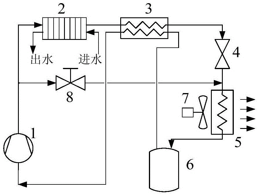
[0033] Embodiment one: see attached figure 1 shown. A carbon dioxide heat pump system includes a compressor, a gas cooler 2 , an intercooler 3 , an expansion valve, an evaporator 5 , a fan, a gas-liquid separator 6 and a defrosting solenoid valve 8 . Wherein, the compressor is a variable frequency compressor 1 , and the fan is a variable frequency fan 7 , which is arranged relative to the evaporator 5 . The expansion valve is an electronic expansion valve 4 . A heating belt is arranged on the gas-liquid separator 6 . The gas cooler 2 is provided with a water circulation pipeline including a water inlet pipe and a water outlet pipe. The carbon dioxide heat pump system is provided with an ambient temperature sensor for detecting the ambient temperature, and the gas cooler 2 is provided with a sensor for detecting the water temperature T out Outlet water temperature sensor, the evaporator 5 is provided with detecting its evaporation temperature T e evaporating temperature se...


PUM


Abstract

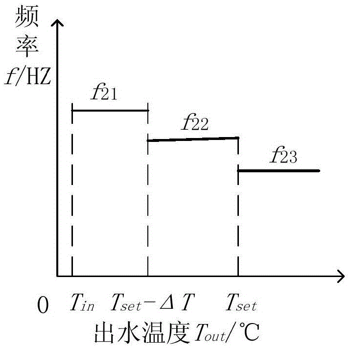
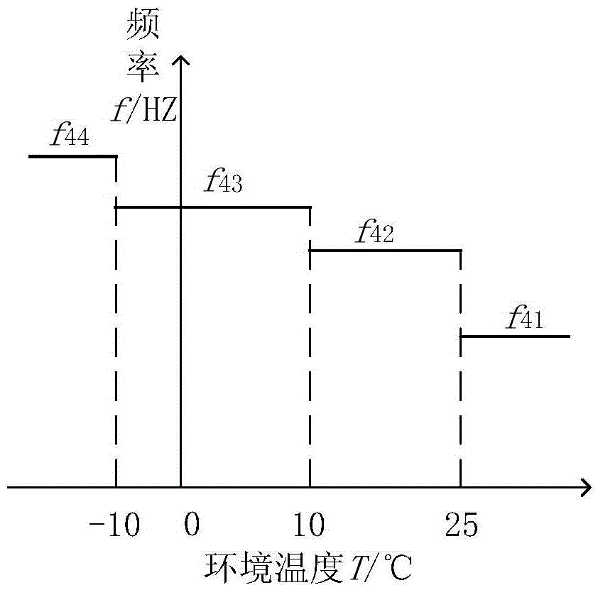
The invention relates to a carbon dioxide heat pump system. The carbon dioxide heat pump system comprises a compressor, a gas cooler, an expansion valve, an evaporator, a draught fan, a gas-liquid separator and a defrosting electromagnetic valve. An exhaust port of the compressor is sequentially connected with the gas cooler, the expansion valve and the evaporator through a pipeline and then backward connected to a gas return port of the compressor to form a heat pump circulating passageway, the exhaust port of the compressor is connected with a gas inlet of the evaporator through a pipeline to form a defrosting bypass, the defrosting electromagnetic valve is arranged on the defrosting bypass, the draught fan is arranged opposite to the evaporator, a water circulating pipeline which comprises a water inlet pipe and a water outlet pipe is arranged in the gas cooler, the compressor is a variable-frequency compressor, and the draught fan is a variable-frequency draught fan. By means of a method for controlling the carbon dioxide heat pump system, running of the variable-frequency compressor and running of the variable frequency draught fan are controlled according to the environmental temperature and the water outlet temperature of the carbon dioxide heat pump system. By means of a fixed-frequency compressor and a fixed-frequency draught fan, the carbon dioxide heat pump system has the advantages of being efficient, capable of saving energy and environmentally friendly, and by means of the control method, the aims of saving energy and being high in speed can be achieved.

Description

technical field [0001] The invention relates to a carbon dioxide heat pump system and a control method adopted by the system. Background technique [0002] As a refrigerant, carbon dioxide has the advantages of non-toxicity, non-combustibility, low cost, zero ODP value, low greenhouse effect, etc., and the heat release process of its transcritical cycle is accompanied by a large temperature glide, which is different from that of water heating. The temperature rise is matched, and hot water up to 90°C can be produced at one time. At the same time, it can also achieve high energy efficiency ratio and hot water temperature under low temperature conditions. However, at present, carbon dioxide heat pumps generally use fixed-frequency compressors, which cannot change the operating conditions of their own units in time according to the load, resulting in energy waste. In addition, there are large starting currents of compressors, rapid decay of unit heating capacity under low-tempe...

Claims


Application Information

Patent Timeline
Patent Type & Authority Patents(China)
IPC IPC(8): F25B30/02F25B49/02F25B47/02
Inventor 汤晓亮熊丹尤军
Owner JIANGSU SUJING GROUP
Learn More