a small circuit breaker

A small circuit breaker, U-shaped technology, applied in the direction of circuit breaker components, etc., can solve the problems of small circuit breakers such as unfavorable arc extinguishing, potential safety hazards, and poor breaking capacity, so as to facilitate arc extinguishing, improve arc extinguishing ability, The effect of strong breaking ability

Active Publication Date: 2016-08-17
DELIXI ELECTRIC
View PDF8 Cites 0 Cited by
  • Summary
  • Abstract
  • Description
  • Claims
  • Application Information

AI Technical Summary

Problems solved by technology

[0006] In order to solve the above problems that the miniature circuit breaker in the prior art is not conducive to arc extinguishing, has poor breaking capacity, and has potential safety hazards, a small circuit breaker that is conducive to arc extinguishing, has strong breaking capacity, and is safe and reliable is provided.

Method used


Image

  • a small circuit breaker
  • a small circuit breaker
  • a small circuit breaker

Examples


Embodiment Construction

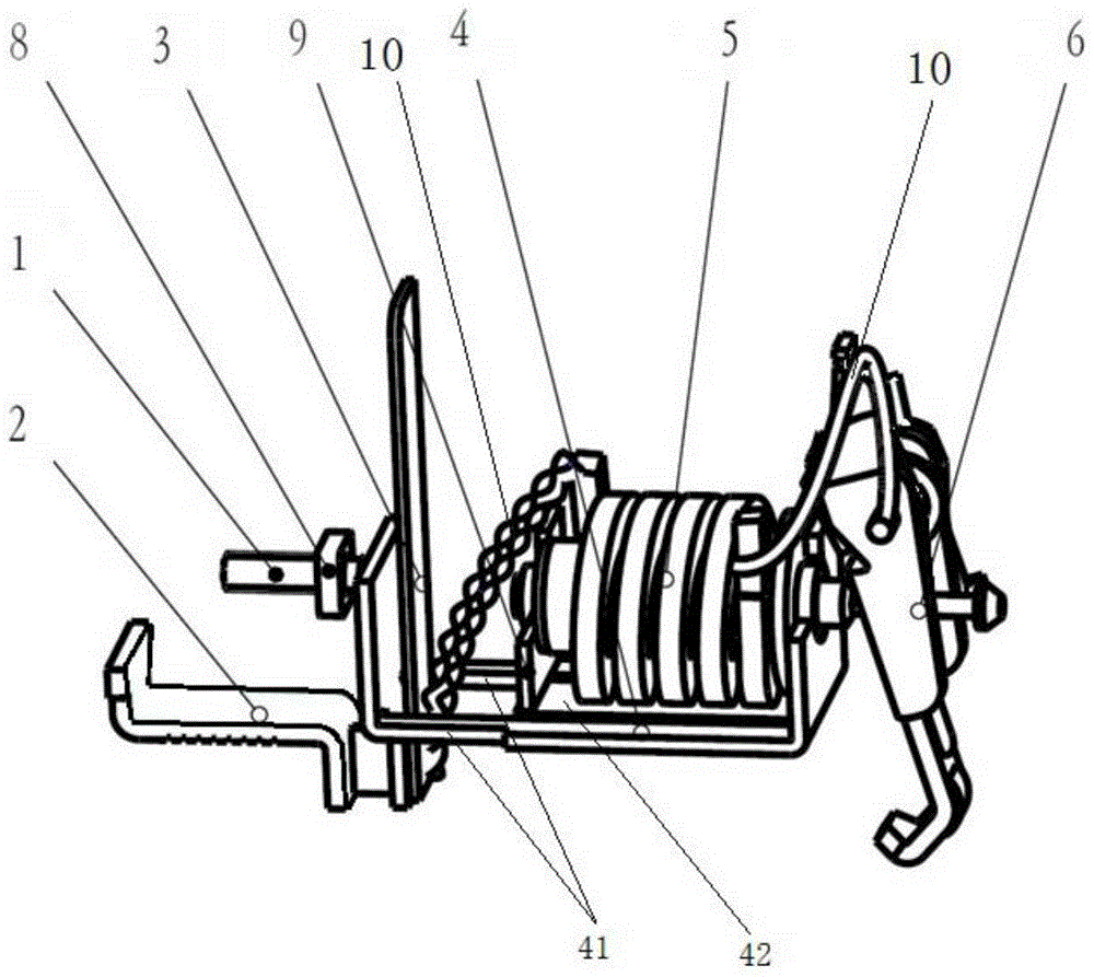
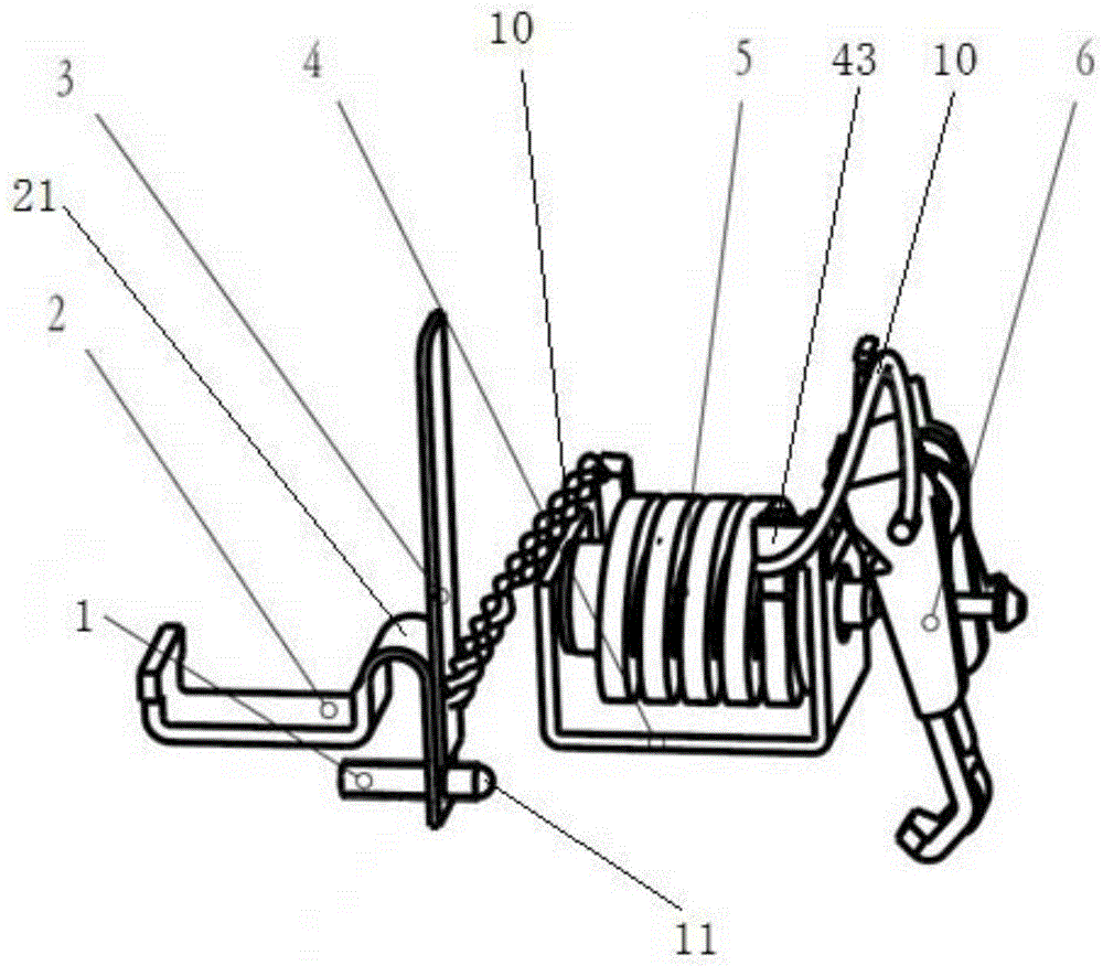
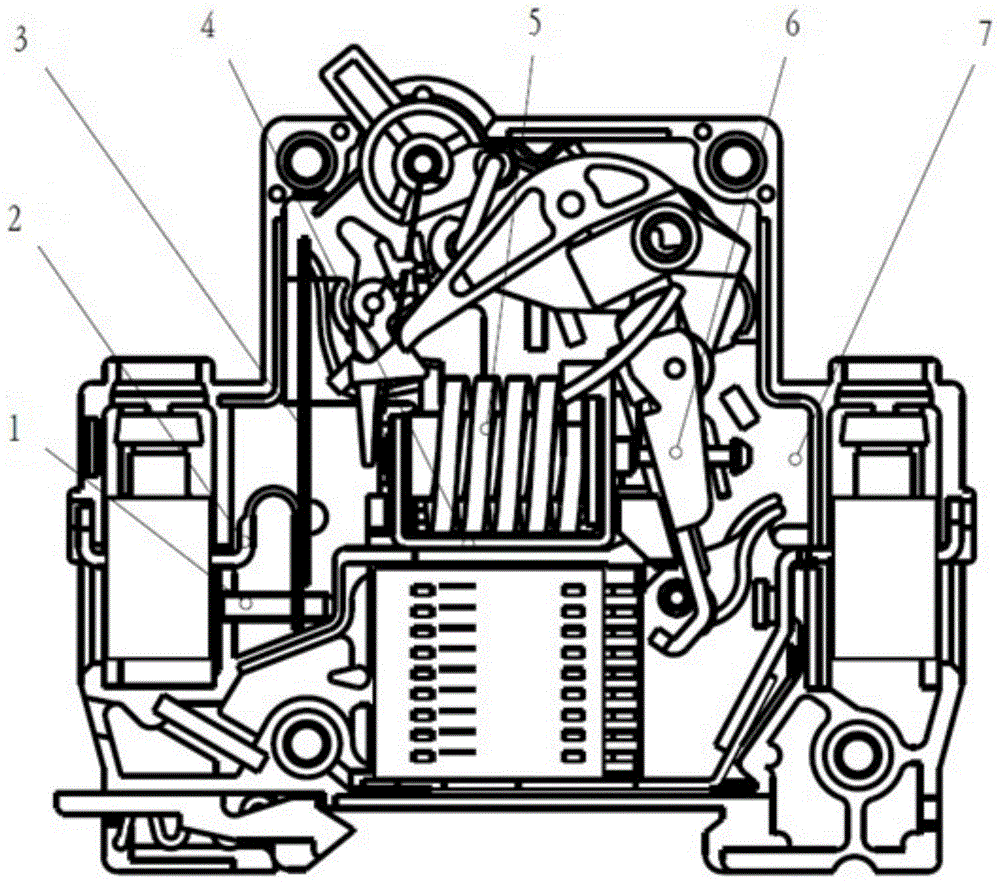
[0031] Such as figure 2 Shown is a preferred embodiment of a miniature circuit breaker of the present invention. The miniature circuit breaker includes a housing 7 and a yoke 4 disposed in the housing 7, a bimetallic strip 3, a moving contact 6, a static contact, a handle, an operating mechanism and other conventional miniature circuit breakers, such as image 3 shown.

[0032] The yoke 4 is U-shaped, and an iron core and a coil 5 sheathed outside the iron core are arranged between two side plates of the yoke 4 . The metal sheet 3 is electrically connected to one end of the coil 5; the movable contact 6 is electrically connected to the other end of the coil 5. In this embodiment, the bimetallic sheet 3 and the movable contact 6 are respectively electrically connected to both ends of the coil 5 through flexible connecting wires 10 . The coil 5 is fixedly connected to the yoke 4 at one end close to the movable contact 6 . The above connections are all realized by welding. ...


PUM


Abstract

A miniature circuit breaker comprises a shell (7), a magnet yoke (4), a bimetallic strip (3) and a moving contact (6), wherein the magnet yoke (4), the bimetallic strip (3) and the moving contact (6) are arranged inside the shell (7), the magnet yoke (4) is U-shaped, an iron core and a coil (5) are arranged between two side plates of the magnet yoke, the iron core is sleeved with the coil, one end of the coil (5) is electrically connected with the bimetallic strip (3), and the other end of the coil (5) is electrically connected with the moving contact (6). The miniature circuit breaker is characterized in that the bimetallic strip (3) is arranged outside the magnet yoke (4) and is not connected with the magnet yoke (4), and the other end of the coil (5) is electrically connected with the side plate, close to the moving contact (6), of the magnet yoke (4). The miniature circuit breaker is beneficial to electric arc extinguishment, strong in breaking capacity, safe and reliable.

Description

technical field [0001] The invention relates to the field of low-voltage electrical technology, in particular to a small circuit breaker. Background technique [0002] Such as figure 1 As shown, in the existing circuit breaker products (DZ47 platform series), the bimetal 3 is welded on the inner wall of one side plate of the yoke 4, and the welding point is located at the lower part of the bimetal 3. The yoke 4 is U-shaped, and its bottom plate is formed with two frames 41 in the direction perpendicular to the side plates, and the bottom plate is formed from the side close to the moving contact 6 to set the bimetal 3- The arc starting plate 42 protruding from the side, there is a gap between the arc starting plate 42 and the two frames 41 . A coil 5 is arranged between the two side plates of the yoke 4, and one end of the coil 5 close to the bimetal 3 is electrically connected to the bimetal 3 through a flexible connecting wire 10, and the other end is connected through an...

Claims


Application Information

Patent Timeline
Patent Type & Authority Patents(China)
IPC IPC(8): H01H73/18
Inventor 潘万军刘丽
Owner DELIXI ELECTRIC
Why Eureka
Try Eureka