Radio frequency detection system for a medical device and process

Active Publication Date: 2008-03-13
DRAGERWERK AG
View PDF3 Cites 2 Cited by
  • Summary
  • Abstract
  • Description
  • Claims
  • Application Information

AI Technical Summary

Benefits of technology

[0005]The basic object of the present invention is therefore to provide a radio frequency detection system

Problems solved by technology

As a result, a radio frequency identification cannot advantageously

Method used


Image

  • Radio frequency detection system for a medical device and process
  • Radio frequency detection system for a medical device and process
  • Radio frequency detection system for a medical device and process

Examples


Embodiment Construction

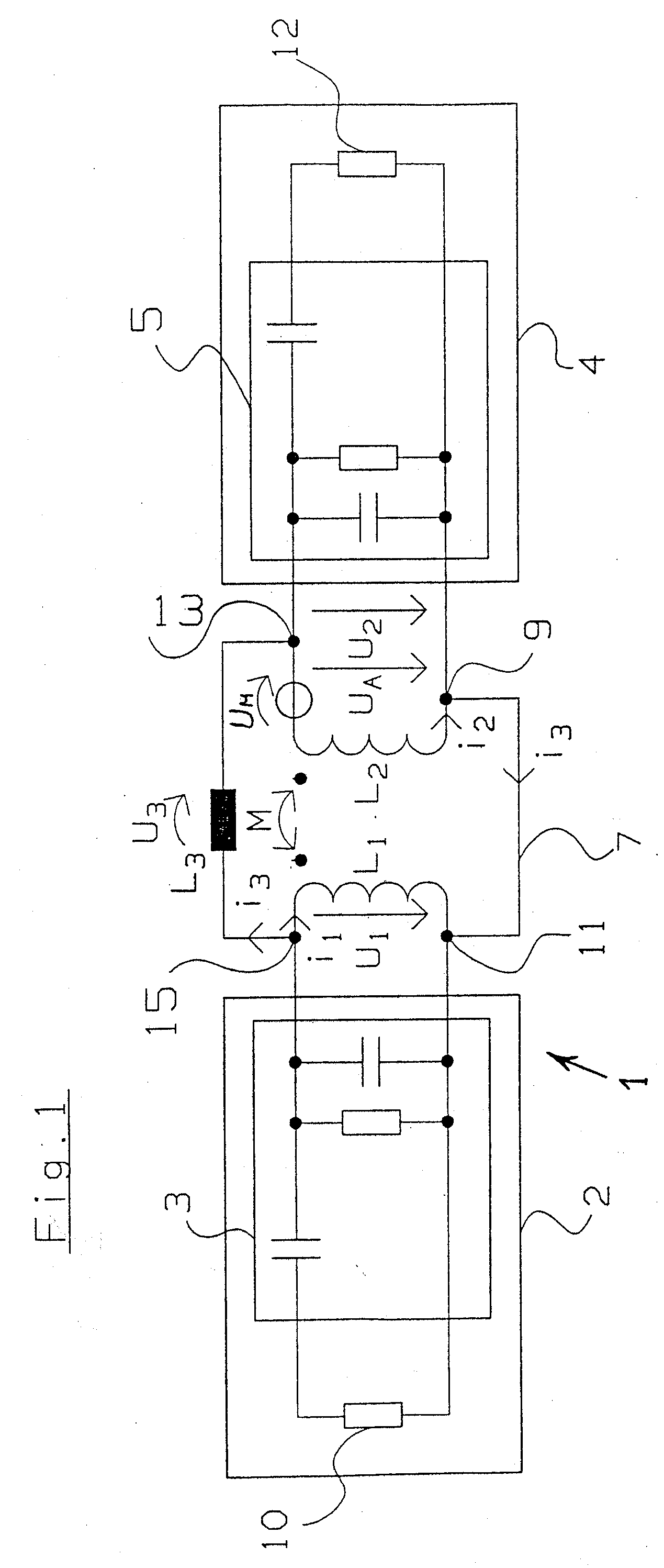
[0038]Referring to the drawings in particular, FIG. 1 schematically shows an exemplary embodiment of a radio frequency detection system 1. The radio frequency detection system 1 comprises a radio frequency detection device 2 and a radio frequency detection device 4. The radio frequency detection device 2 has a compensation member 3 and an antenna L1 connected to the compensation member 3. The compensation member 3 is connected on the input side to a transmitter 10 for generating a radio frequency signal with a radio frequency current. The radio frequency detection device 4 has a compensation member 5 and a transmitter 12 for generating a radio frequency signal with a radio frequency current. The compensation member 5 is connected to an antenna L2 on the output side and is connected to the transmitter 12 on the input side.

[0039]The radio frequency detection system 1 also has a compensation member L3. The compensation member L3 is designed as an inductance, a first terminal of the com...


PUM


Abstract

A radio frequency detection system is provided that includes at least two radio frequency detection devices, which have an antenna each with a detection range for a radio frequency identification and detect the radio frequency identification information provided in the detection range. The radio frequency detection system is designed to attenuate a detection range of a detecting radio frequency detection device in the detection range of the at least one other radio frequency detection device by means of a compensation member such that the radio frequency identification cannot be detected by the detecting radio frequency detection device in the detection area of the at least one other radio frequency detection device. The compensation member feeds a compensation current to the at least one other antenna to generate an opposing magnetic field, which attenuates or extinguishes the magnetic field of the detecting antenna in the at least one other detection range, by the at least one other antenna in the at least one other detection range.

Description

CROSS REFERENCE TO RELATED APPLICATIONS[0001]This application claims the benefit of priority under 35 U.S.C. § 119 of German Patent Application DE 10 2006 041 914.6 filed Sep. 7, 2006, the entire contents of which are incorporated herein by reference.FIELD OF THE INVENTION[0002]The present invention pertains to a radio frequency detection system especially for a medical device with at least two radio frequency detection devices, which have an antenna each with a detection range for a radio frequency identification. The radio frequency detection devices are designed each to detect the radio frequency identification and an identification information made available by these in the detection range.BACKGROUND OF THE INVENTION[0003]The problem arises in radio frequency detection systems with a plurality of antennas, in which one of the plurality of antennas is assigned to at least one radio frequency detection device, that spatial or local separation of detection ranges of antennas that a...

Claims


Application Information

Patent Timeline
IPC IPC(8): H04M1/00
CPCH04B5/0075
Inventor SCHERMEIER, OLAFSTEEGER, MARKUS
Owner DRAGERWERK AG
Why Eureka
Try Eureka