Multi-wave-beam antenna system

A multi-beam antenna and antenna unit technology, applied in the direction of antennas, electrical components, etc., to achieve the effect of suppressing the amplitude

Active Publication Date: 2014-03-26
HUAWEI TECH CO LTD
View PDF3 Cites 10 Cited by
  • Summary
  • Abstract
  • Description
  • Claims
  • Application Information

AI Technical Summary

Problems solved by technology

[0006] The multi-beam antenna system in the prior art can only use a 4*4 Butler matrix to form multi-beams, and cannot use other types of Butler matrices to form multi-beams
Moreover, since the radio frequency signals output by the 4+M output terminals of the power secondary distribution circuit have a phase difference, at least one of the multi-beams formed by the 4+M multi-beam antenna units has no beam pointing directly forward

Method used


Image

  • Multi-wave-beam antenna system
  • Multi-wave-beam antenna system
  • Multi-wave-beam antenna system

Examples


Embodiment 1

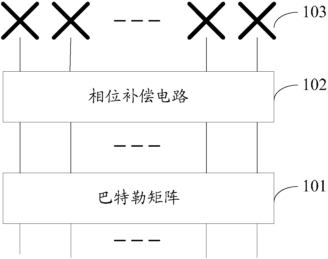
[0032] The invention provides a multi-beam antenna system. see figure 1 , the system includes: a Butler matrix 101 , a phase compensation circuit 102 and at least a first number of multi-beam antenna units 103 .

[0033] Wherein, the Butler matrix 101 includes a first number of output ends; the phase compensation circuit 102 includes a first number of input ends and a first number of output ends; a multi-beam antenna unit 103 includes an input end and an output end.

[0034] Wherein, each output end of Butler matrix 101 is connected with each input end of phase compensation circuit 102 respectively; Each output end of phase compensation circuit 102 is connected with a multi-beam antenna unit 103, and the output end of multi-beam antenna unit 103 forms Multiple beams.

[0035] Wherein, in the embodiment of the present invention, taking the first numerical value of 8 as an example for illustration, the Butler matrix 101 includes 8 output terminals, the phase compensation circu...

Embodiment 2

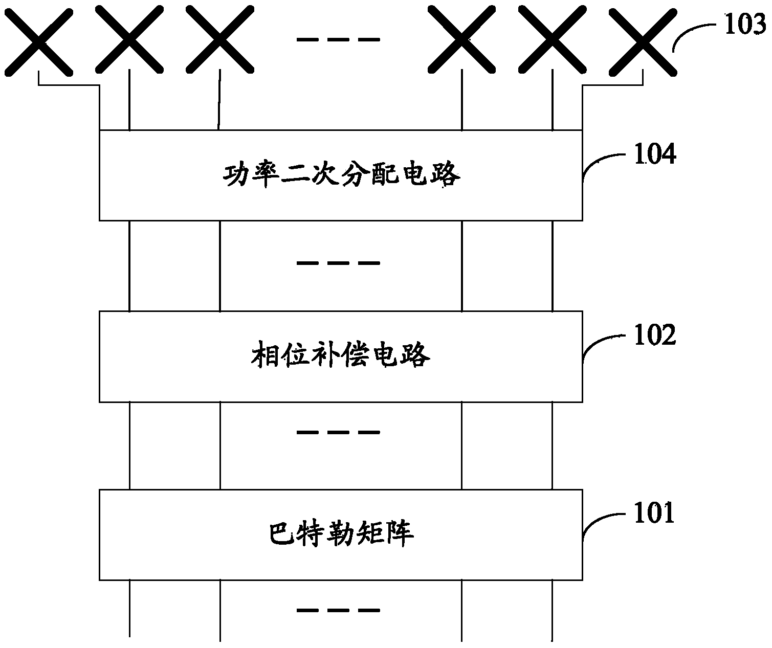
[0039] The invention provides a multi-beam antenna system. see figure 2 , the system includes: a Butler matrix 101, a phase compensation circuit 102, and a plurality of multi-beam antenna units 103 with a second numerical value, the system also includes: a power distribution circuit 104, the second numerical value is greater than the first numerical value, and the second numerical value is smaller than the first numerical value 2 times the value; the power distribution circuit 104 includes a first number of input terminals and a second number of output terminals.

[0040] Wherein, each output end of Butler matrix 101 is connected with each input end of phase compensation circuit 102 respectively; Each output end of phase compensation circuit 102 is connected with each input end of power distribution circuit 104 respectively; Power distribution circuit 104 Each output end of , is connected to a multi-beam antenna unit 103 .

[0041] Wherein, the Butler matrix 101 includes tw...


PUM


Abstract

The invention belongs to the technical field of wireless communication and discloses a multi-wave-beam antenna system which comprises a Butler matrix, a phase compensation circuit and at least first numerical value of multi-wave-beam antenna units. The Butler matrix comprises a first numerical value of output ends, the phase compensation circuit comprises a first numerical value of input ends and a first numerical value of output ends, each output end of the Butler matrix is connected with the corresponding input end of the phase compensation circuit, and each output end of the phase compensation circuit is connected with one multi-wave-beam antenna unit. The phase compensation circuit is added in the multi-wave-beam antenna system, and integral deflection of multiple wave beams formed by the Butler matrix can be realized, so that wave beams directing right ahead are formed.

Description

technical field [0001] The invention relates to the technical field of wireless communication, in particular to a multi-beam antenna system. Background technique [0002] With the rapid development of wireless communication technology, wireless communication has been widely used in people's production and life. For example, wireless communication technology is applied to multi-beam antennas, and multi-beam antennas are used to implement parallel transmission of wireless communication signals. [0003] A multi-beam antenna system is provided in the prior art, which may include a Butler matrix, a secondary power distribution circuit, and 4+M multi-beam antenna units, where M is an integer greater than or equal to 1 and less than or equal to 4. Wherein, the Butler matrix includes 4 input terminals and 4 output terminals; the power secondary distribution circuit includes 4 input terminals and 4+M output terminals. Wherein, each output end of the Butler matrix is ​​respectively...

Claims


Application Information

Patent Timeline
Patent Type & Authority Applications(China)
IPC IPC(8): H01Q23/00H01Q25/00
Inventor 杨朝辉赵建平王琳琳罗伟
Owner HUAWEI TECH CO LTD
Why Eureka
Try Eureka