Switchgear cabinet for tool-less floor panel mounting

A switchgear and baseplate technology, applied in substation/switch layout details, electrical components, electrical equipment structural parts, etc., can solve the problem of easy loss of clamping parts and clamping bolts, and achieve the effect of simplifying installation or disassembly

Active Publication Date: 2014-03-26
RITTALWERK RUDOLF LOH GMBH & CO KG
View PDF11 Cites 2 Cited by
  • Summary
  • Abstract
  • Description
  • Claims
  • Application Information

AI Technical Summary

Problems solved by technology

The known switchgear also has the disadvantage that the clamping elements and clamping bolts are small, easily lost parts

Method used


Image

  • Switchgear cabinet for tool-less floor panel mounting
  • Switchgear cabinet for tool-less floor panel mounting
  • Switchgear cabinet for tool-less floor panel mounting

Examples


Embodiment Construction

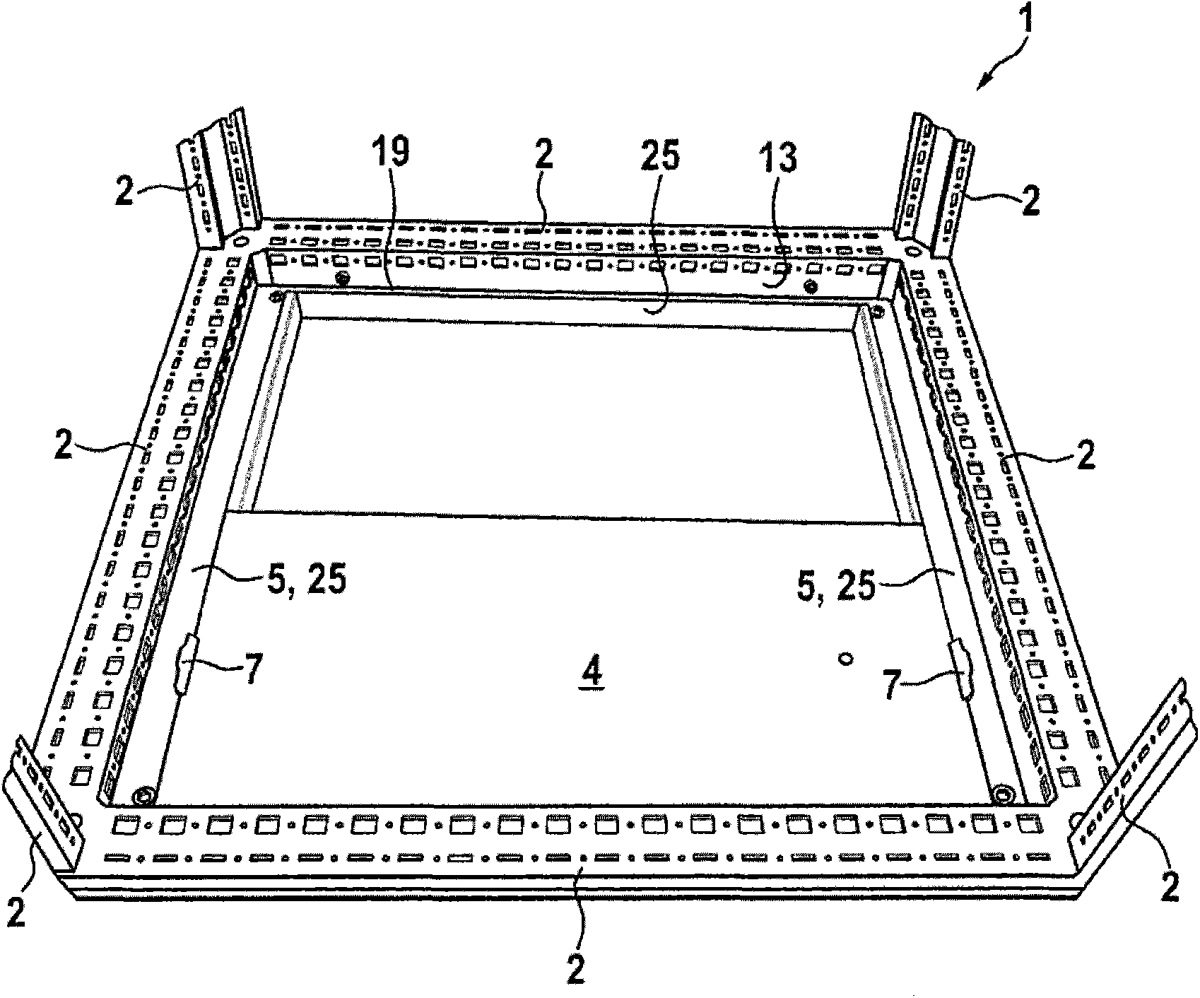
[0029] figure 1 A preferred embodiment of the present invention is shown. In this embodiment, the mounting rail 5 is provided by a bottom groove 25, wherein the mounting rail 5 is composed of two opposite frame members of the bottom groove 25. The two frame members of the bottom groove 25 that provide the mounting rail 5 are connected to each other through the other two frame members arranged perpendicular to them, so that the bottom groove 25 forms a substantially right-angled frame. The frame arm 2 is designed as a hollow profile, wherein the bottom groove 25 has at least one fixed connecting piece extending vertically through the opening to the inside of the hollow profile. The fixed connecting piece is bolted to the vertical profile surface 13 of the frame arm 2. The bottom plate 4 is frictionally connected with the mounting rail 5 by means of a locking member 7 arranged on the mounting rail 5 opposite to each other.

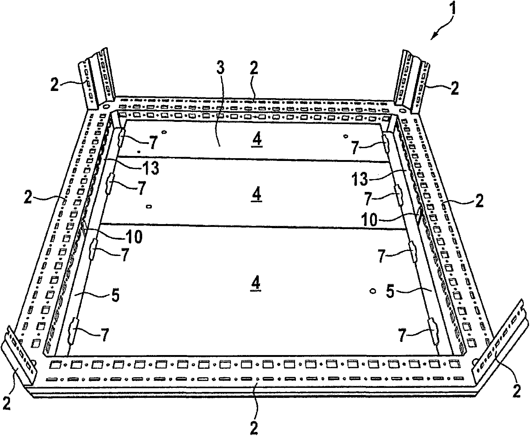
[0030] figure 2 The frame of the switch cabinet 1 and ...


PUM


Abstract

The present invention relates to a switchgear cabinet (1). The switchgear cabinet comprises a frame formed by frame portions (2), an open bottom side (3) may be sealed by at least one bottom plate (4), wherein A mounting rail (5) with a horizontal bearing face (6) is extended along two opposite frame portions (2) of the bottom side (3). The bottom plates may be placed on the bearing faces, and the mounting rail (5) has a detent element (7) with a locking pawl (8) which is arranged at a vertical distance from the bearing face (6). The locking pawl (8) is moved in forward and backward directions between an open position in which the bottom plate (4) is released for the removal, and a closed position in which the bottom plate (4) is supported between the bearing face (6) and the locking pawl (8). According to one embodiment, the mounting rail (5) is provided by bottom grooves.

Description

Technical field [0001] The present invention relates to a switch cabinet capable of installing a bottom plate without tools. It includes a frame composed of frame arms. The open bottom surface can be closed by at least one bottom plate, wherein two opposite frame arms along the bottom surface respectively extend one For the mounting rail with a supporting surface, the bottom plate can be placed on the supporting surface, and the mounting rail is provided with a locking member, and the locking member includes a locking pawl arranged perpendicular to the supporting surface. For switch cabinets arranged in rows, the mounting rails can also extend along the opposite frame arms of adjacent switch cabinets. Such a switch cabinet is known from DE44 46 223C1. Similar switch cabinets are known from DE101 47 342A1, DE197 30 430A1 and DE10 2007 014 786A1. Background technique [0002] In the switchgear disclosed by DE197 30 430A1, the bottom plate is connected to the bottom surface of the...

Claims


Application Information

Patent Timeline
Patent Type & Authority Applications(China)
IPC IPC(8): H02B1/32
CPCH05K7/183H02B1/303H02B1/305H02B1/301
Inventor R·本纳R·布朗
Owner RITTALWERK RUDOLF LOH GMBH & CO KG
Why Eureka
Try Eureka