Automatic rail cable machining device

An automatic processing and track technology, applied in the direction of cable installation, cable installation device, equipment for dismantling/armoring cables, etc., can solve the problems of inability to strip a large length, high labor intensity, easy damage to the cable core, etc. The effect of labor intensity, improved peeling efficiency, improved reliability and stability

Active Publication Date: 2014-03-26
JIANGSU HENGTONG WIRE & CABLE TECH
View PDF4 Cites 3 Cited by
  • Summary
  • Abstract
  • Description
  • Claims
  • Application Information

AI Technical Summary

Problems solved by technology

The main problems are low efficiency, easy damage to the cable core,

Method used


Image

  • Automatic rail cable machining device
  • Automatic rail cable machining device
  • Automatic rail cable machining device

Examples


Embodiment

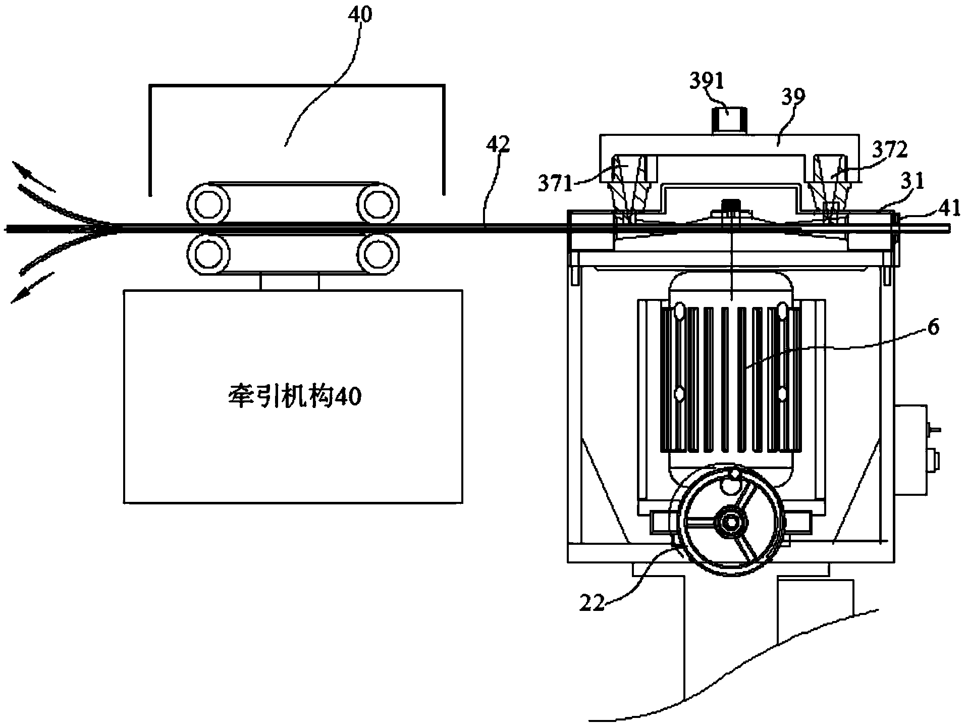
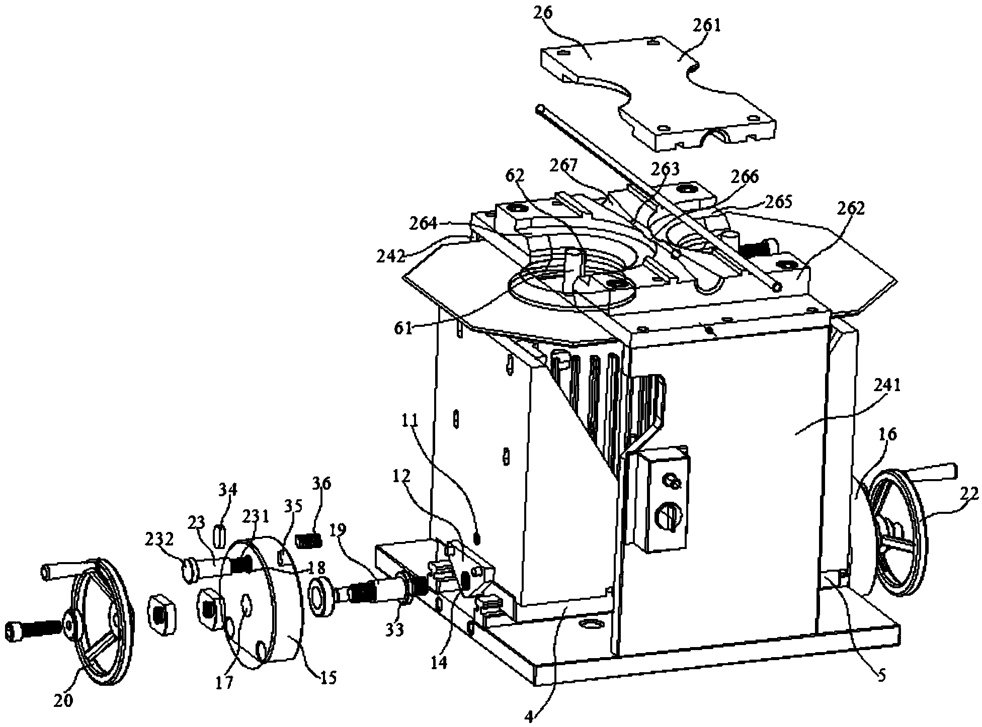
[0029] Embodiment: an automatic processing device for a track cable, the track cable 42 has a metal sheath layer, including: a base 1, a fixed bottom plate 2, a column 3 fixed between the base 1 and the fixed bottom plate 2, Left and right motor support 4,5, 2 motors 6 and traction mechanism 40; One is installed on the left motor support 4 in described 2 motors 6, and another is installed on the right motor support 5, this left and right motor support The lower surfaces of 4 and 5 are respectively fixed with two sliders 7 in parallel, and two line rails 8 are arranged in parallel on the fixed bottom plate 2, and the line rails 8 are embedded in the left and right motor brackets 4 and 5 respectively to slide In the groove 71 of the block 7, the respective outer sides of the left and right motor brackets 4, 5 are respectively fixed with left and right baffles 9, 10 with adjusting screw holes 11, and the respective outer sides of the left and right baffles 9, 10 are Left and righ...


PUM


Abstract

The invention discloses an automatic rail cable machining device which comprises a fixed base plate, a left motor support, a right motor support, two motors and a hauling mechanism, wherein a left baffle provided with an adjusting threaded hole is fixed on the outer side of the left motor support, a right baffle provided with an adjusting threaded hole is fixed on the outer side of the right motor support, a left connecting plate provided with a driving threaded hole is fixed on the outer side of the left baffle, a right connecting plate provided with a driving threaded hole is fixed on the outer side of the right baffle, the left connecting plate and the right connecting plate are located between two linear guide rails, a ground groove is formed in the end face, opposite to the left baffle, of a left fixed base, a ground groove is formed in the end face, opposite to the right baffle, of a right fixed base, two springs are mounted on screws of two limiting bolts in a sleeved mode respectively and located between the left fixed base and the left baffle and between the right fixed base and the right baffle respectively, a left oiling groove and a right oiling groove are formed in a shield, and the left oiling groove and the right oiling groove are located over a left round cutting piece and a right round cutting piece respectively. According to the automatic rail cable machining device, cutting depth can be adjusted dynamically, parameters can be adjusted flexibly by operators according to the characteristics of products and working conditions, generality is high, a cable core is further effectively protected, and danger factors existing in manual or mechanical cutting are also avoided.

Description

technical field [0001] The invention relates to a cable processing device, in particular to an automatic processing device for track cables. Background technique [0002] In order to meet the requirements of electromagnetic field shielding and anti-mechanical damage in various complex environments, wire and cable are equipped with copper, aluminum, steel and other metal materials or their alloys in the product design and manufacturing process. The metal shielding sheath composed of materials, that is, the cable metal sheath (also known as the metal sheath), the metal sheath is wrapped with various metal strips, longitudinally wrapped, welded into a tubular or thin round wire wrapped and other structures The form is set on the outer layer of the cable core. For cables with such a metal sheath, in the process of manufacture, installation and maintenance, the metal sheath needs to be cut and stripped before the cable core is inspected, spliced ​​and installed. Due to the exis...

Claims


Application Information

Patent Timeline
IPC IPC(8): H02G1/12
CPCH02G1/126H02G1/127H02G1/1297
Inventor 余建朝王国权沈建新李宁范建华孙明华曹卫忠刘党荣
Owner JIANGSU HENGTONG WIRE & CABLE TECH
Why Eureka
Try Eureka