
Quick lifting method for online drawing rotor of large motor
A technology for large motors and motor rotors, applied in the manufacture of stator/rotor bodies, etc., can solve problems such as low efficiency, many jacking times, and high cost, and achieve the effect of overcoming defects
- Summary
- Abstract
- Description
- Claims
- Application Information
AI Technical Summary
Problems solved by technology
Method used
Image

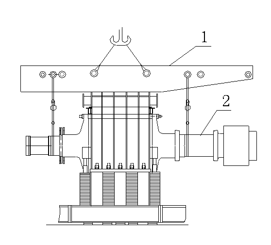
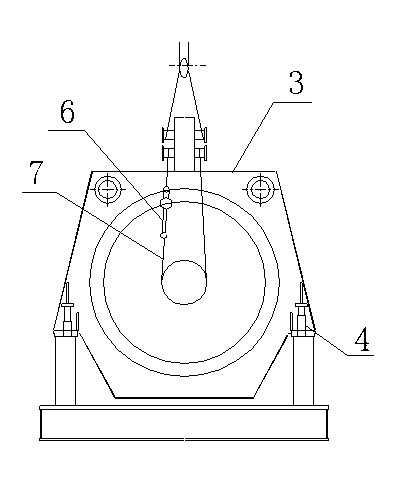
Examples
Embodiment Construction
[0019] The present invention is further illustrated below by specific examples.
[0020] Such as figure 1 , figure 2 Shown:
[0021] A fast jacking method for online rotor extraction of a large motor, comprising the following steps:
[0022] Step 1. Remove and lift the universal joint shaft of the motor;
[0023] Step 2. Dismantling of electrical lines and instruments;
[0024] Step 3. Remove the upper cover and the upper tile of the bearing housings at both ends of the motor, remove the motor cover and accessories, and remove the motor stator anchor bolts;
[0025] Step 4. Remove and lift the motor encoder, thrust bearing and accessories;
[0026] Step 5: Assemble the motor to the long shaft;
[0027] It also includes a rotor suspension beam 1, an inverted chain 6, a steel cable 7 and the following steps,
[0028] Step 6: Lift the rotor beam 1 with a crane, set the rotor beam 1 on the top of the motor stator 3 and level it, then hang 6 chains and steel cables 7 on bot...
PUM
 Abstract
Description
Claims
Application Information