Auto-reverse camera

An automatic flip, camera technology, applied in the direction of image communication, TV, color TV, etc., can solve the problems of increasing product cost, unable to achieve Selfie, unable to satisfy people with shooting effect, etc., and achieve the effect of saving production cost.

Inactive Publication Date: 2014-03-26
路宽
View PDF0 Cites 22 Cited by
  • Summary
  • Abstract
  • Description
  • Claims
  • Application Information

AI Technical Summary

Problems solved by technology

However, at present, the cameras of portable devices in the prior art are usually back-illuminated, which can hardly realize self-portraits. Even if some products can realize self-portraits, the shooting effect cannot satisfy people due to the low pixel of the camera.
In order to achieve a good selfie or video call effect, you can set the front camera, but this will greatly increase the cost of the product

Method used


Image

  • Auto-reverse camera
  • Auto-reverse camera
  • Auto-reverse camera

Examples


Embodiment 1

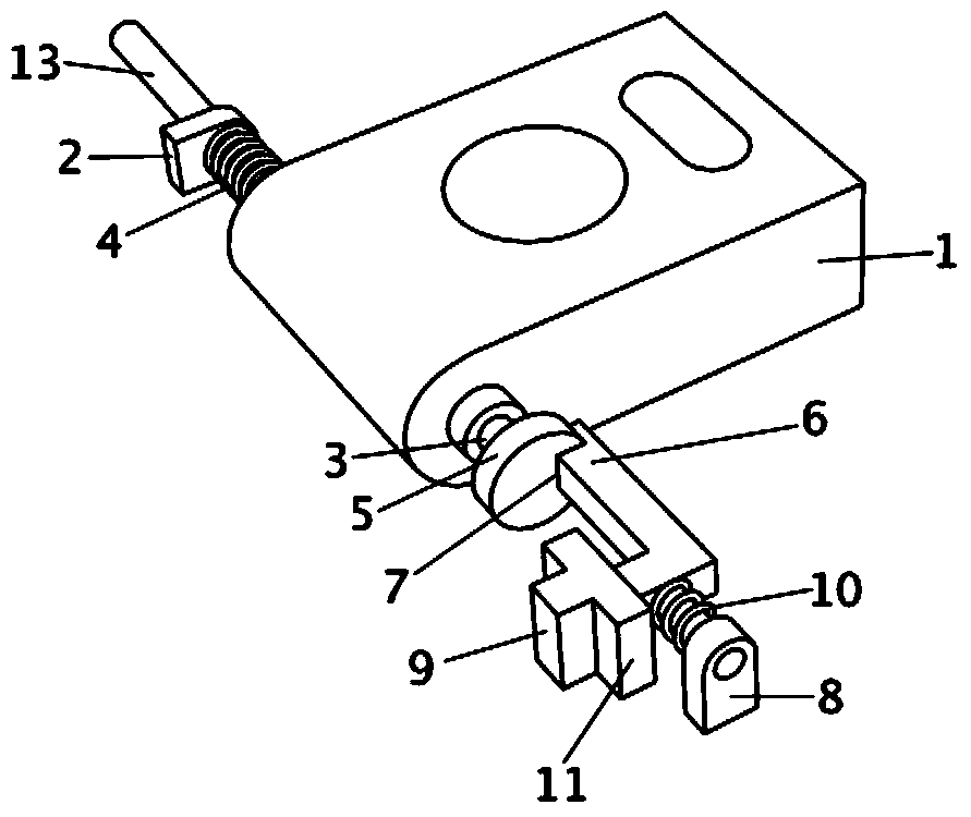
[0028] The automatic flip camera provided in this embodiment is as follows: figure 1 and Figure 5 as shown in:

[0029] One side of the camera body 1 is provided with a first installation end 2, the first installation end 2 is provided with a through hole and is fixedly connected with the mobile terminal equipment, the first installation end 2 is provided with a connecting column 13, and a torsion spring 4 is arranged on the connecting column 13 And the connecting column 13 passes through the through hole of the first mounting end 2 , and the two ends of the torsion spring 4 are respectively fixed on the first mounting end 2 and the camera body 1 . When the camera body 1 is not locked by the locking module, the camera body 1 can be turned over automatically by the action of the torsion spring 4 .

[0030] The connection column 13 is provided with a line, and the line is connected to the camera circuit. One end of the connection column 13 is inserted into the camera body 1,...

Embodiment 2

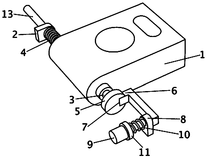
[0040] The automatic flip camera provided in this embodiment is as follows: figure 2 as shown in:

[0041] The structure of the automatic flip camera in this embodiment is similar to that of Embodiment 1, the difference is only in the locking module, specifically, the limit post 6 of the locking module is perpendicular to the other end of the connecting rod, and is connected to the operating block 9 On the same side of the rod, the second installation end 8 is directly arranged on the connecting rod, close to the position of the operation block 9 , and a spring 10 is arranged between the second installation end 8 and the blocking piece 11 . By pressing the operation block 9, the limit column 6 can be driven to break away from the limit groove 7 via the connecting rod, and the camera body 1 can be flipped; Operation block 9 can be reset.

[0042] In this embodiment, the limit post 6 is located at the side of the outer wall of the limit block 5 after breaking away from the li...

Embodiment 3

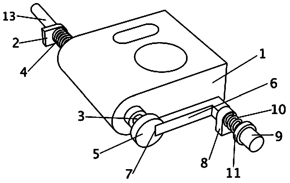
[0045] The automatic flip camera provided in this embodiment is as follows: image 3 as shown in:

[0046] The structure of the automatic flipping camera in this embodiment is similar to that of Embodiment 2, the only difference being that on the locking module, specifically, the limit post 6 of the locking module is located at the other end of the connecting rod, and is coaxially arranged integrally with the connecting rod. The integral structure of the limiting column 6 and the connecting rod is L-shaped. Likewise, the second installation end 8 is directly arranged on the connecting rod, close to the position of the operation block 9 , and a spring 10 is arranged between the second installation end 8 and the blocking piece 11 . By pressing the operation block 9, the limit column 6 can be driven to break away from the limit groove 7 via the connecting rod, and the camera body 1 can be flipped; Operation block 9 can be reset.

[0047] In this embodiment, after the limit pos...


PUM


Abstract

The invention discloses an auto-reverse camera which comprises a camera body and a locking module, wherein the camera body and the locking module are respectively provided with an installation end, the camera body is placed in an accommodating space of mobile terminal equipment, a limiting groove is formed in the camera body, a limiting column is arranged on the locking module, the camera body is locked in the accommodating space by the locking module when the limiting column is clamped in the limiting groove, the camera body is released by the locking module when the limiting column is disengaged from the limiting groove, and a rear camera is changed to a front camera when the camera body is reversed out automatically from the accommodating space. According to the auto-reverse camera, the camera body is mounted on the terminal equipment in a rotary mode and can be locked or released by the locking module, automatic reversing of the camera body can be achieved after the camera body is released, a front camera does not need to be arranged specially, self-photographing or video call can be realized perfectly, multiple purposes can be realized, and therefore production cost of the terminal equipment is saved.

Description

technical field [0001] The invention relates to image acquisition technology, in particular to an automatic flip camera. Background technique [0002] With the advancement of technology and the development of society, people's demand for photography is getting higher and higher. It is no longer limited to shooting for others. Many people hope that the products they buy can realize the Selfie function; at the same time, with the With the wide application of 3G and 4G communication technologies, video calls are becoming more and more common. However, at present, the cameras of portable devices in the prior art are usually back-illuminated, which can hardly realize self-portraits. Even if some products can realize self-portraits, the shooting effect cannot satisfy people because the camera pixels are not high. In order to achieve a good selfie or video call effect, a front camera can be set, but this will greatly increase the cost of the product. Contents of the invention ...

Claims


Application Information

Patent Timeline
Patent Type & Authority Applications(China)
IPC IPC(8): H04N5/225F16M11/06F16M11/16F16M11/18
CPCG03B17/02H04N23/51H04N23/57
Inventor 路宽
Owner 路宽
Why Eureka
Try Eureka