Guide mechanism and method in parallel flow air conditioner fin die

A technology of air-conditioning fins and parallel flow, which is applied in the field of parallel-flow air-conditioning fin molds to achieve precise guiding effects

Active Publication Date: 2015-11-18
WUXI MICRO RES
View PDF6 Cites 0 Cited by
  • Summary
  • Abstract
  • Description
  • Claims
  • Application Information

AI Technical Summary

Problems solved by technology

For the guiding structure of the traditional tubular fin mold, see figure 1 , including the guiding nail 200 fixed on the upper die 100, the guide plate 300, the unloading sleeve 400 elastically connected to the guide plate 300, the lower module 500, etc., when the punch slider drives the upper die 100 downward, the guiding nail The head of 200 first enters the flanging hole on the tubular fin 600 for alignment, the upper die 100 continues to move downward, the unloading sleeve 400 is pressed back into the guide plate 300 by the lower module 500 and the tubular fin 600, and guides The straight part of the straight nail 200 enters the flange hole on the tubular fin 600 for guiding. However, since the structure of the parallel flow fin is completely different from that of the traditional tubular fin, there is no turning of the tubular fin. The side hole structure, therefore, it is necessary to design a special guiding mechanism for the parallel flow fin structure

Method used


Image

  • Guide mechanism and method in parallel flow air conditioner fin die
  • Guide mechanism and method in parallel flow air conditioner fin die
  • Guide mechanism and method in parallel flow air conditioner fin die

Examples


Embodiment Construction

[0017] The specific implementation manner of the present invention will be described below in conjunction with the accompanying drawings.

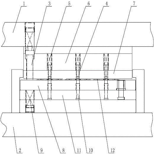
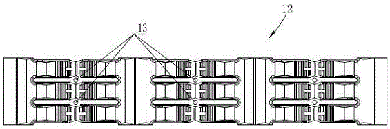
[0018] See figure 2 , image 3 , the guiding mechanism in the parallel flow air-conditioning fin mold of the present invention comprises an upper mold base 1 and a lower mold base 2, the upper mold base 1 is elastically connected with an upper driving rod 3, and the unloading sleeve 4 is elastically connected by a spring-5. Installed on the upper fixed plate 6, and the unloading sleeve 4 passes through the guide plate 7, the upper fixed plate 6 and the guide plate 7 are installed on the upper mold base 1, and the upper driving rod 3 passes through the upper fixed plate 6 and the guide plate 7; The lower floating material plate 8 is elastically mounted on the lower mold base 2 through the spring two 9, the guiding nail 10 is fixedly installed in the lower fixing plate 11, the lower fixing plate 11 is installed on the lower mold base 2, an...


PUM


Abstract

The invention discloses a pilot mechanism, which is especially arranged by aiming at a parallel flow fin. Firstly, a technical pilot hole is processed on the transection position of a parallel flow fin material belt. According to the pilot mechanism disclosed by the invention, the material belt is subjected to secondary piloting. The pilot mechanism comprises an upper die holder and a lower die holder, wherein the upper die holder is elastically connected with an upper beating rod; a discharging sleeve is elastically installed on an upper fixed plate by a first spring; the discharging sleeve passes through a guide plate; the upper fixed plate and the guide plate are installed on the upper die holder; the upper beating rod is penetrated out of the upper fixed plate and the guide plate; a lower material floating plate is installed on the lower die holder by a second spring; a pilot nail is fixedly arranged in a lower fixed plate; the lower fixed plate is installed on the lower die holder; the lower material floating plate is positioned above the lower fixed plate; the position, which corresponds to the pilot nail, on the lower material floating plate is provided with a through hole through which the pilot nail passes; the pilot nail is opposite to the position of the discharging sleeve; the discharging sleeve is provided with a groove of which the opening faces downwards; the groove is provided with the arc-shaped opening. According to the invention, the precise piloting of the parallel flow fin material belt can be realized by two-time piloting.

Description

technical field [0001] The invention relates to a parallel-flow air-conditioning fin mold, in particular to a guiding mechanism and a guiding method in a parallel-flow air-conditioning fin continuous mold. Background technique [0002] The heat exchanger is the core component of the air conditioner. The heat exchange effect directly affects the overall performance of the air conditioner. It is gradually developing towards compactness, light weight, and high performance. Compared with traditional tubular fins, parallel flow fins are due to Its compact shape, high heat transfer rate, light weight, and high reliability are gradually becoming the mainstream products of heat exchangers. Air-conditioning fins are stamped by special fin dies. In the process of producing fins with continuous step dies, good and precise guidance of the fin material strips is the smooth processing of the fin continuous step dies and the fins One of the prerequisites for film product quality. For the...

Claims


Application Information

Patent Timeline
Patent Type & Authority Patents(China)
IPC IPC(8): B21D37/12
Inventor 王静娴陈亮
Owner WUXI MICRO RES
Why Eureka
Try Eureka