Automatic welding trolley, automatic welding device and control method of automatic welding device

An automatic welding and trolley technology, which is applied in the direction of auxiliary devices, welding equipment, auxiliary welding equipment, etc., can solve problems such as limited travel, achieve the effects of simplifying the structure, ensuring welding quality, and ensuring steering accuracy

Pending Publication Date: 2020-08-14
CHENGDU ALANGTECH
View PDF1 Cites 3 Cited by
  • Summary
  • Abstract
  • Description
  • Claims
  • Application Information

AI Technical Summary

Problems solved by technology

[0007] The purpose of the present invention is to provide an automatic welding trolley and an automatic welding device in view of the problem that the stroke is limited during use in the automatic welding process using a welding machine or a welding robot in the prior art

Method used


Image

  • Automatic welding trolley, automatic welding device and control method of automatic welding device
  • Automatic welding trolley, automatic welding device and control method of automatic welding device
  • Automatic welding trolley, automatic welding device and control method of automatic welding device

Examples


Embodiment 1

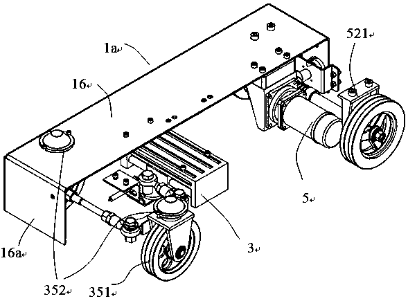
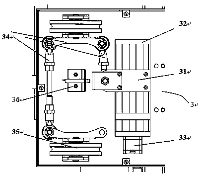
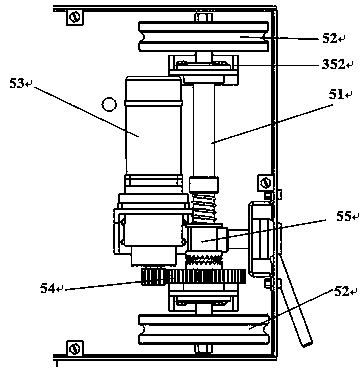
[0062] This embodiment provides an automatic welding trolley 1a, such as figure 1 As shown, it includes a walking component 5 for controlling the walking of the trolley, and a steering component 3 for controlling the steering of the trolley. Both the walking component 5 and the steering component 3 are installed on the frame support plate 16, so that the three form The trolley structure, the frame support plate 16 is a long strip structure, the steering component 3 and the walking component 5 are arranged under the frame support plate 16, and the steering component 3 is located in front of the traveling direction of the trolley. The component 5 is located at the rear of the traveling direction of the trolley. The traveling component 5 and the steering component 3 are arranged independently. The top of the frame support plate 16 is used to install weld detection components and welding components. The welding components are used for automatic butt welding. For welding, the weld de...

Embodiment 2

[0069] This embodiment provides an automatic welding device 1A, such as Figure 4 As shown, including the automatic welding trolley 1a in Example 1, the automatic welding trolley 1a is equipped with a weld detection component 1 and a welding component for automatic welding of the weld 4, and the weld detection component 1 is used For detecting weld information, the welding component is correspondingly arranged on the path of the weld detection component 1 for the weld detection, the welding component includes a welding controller 8, and the welding controller 8 is in communication connection with the weld detection component 1 , And control the steering component 3 and the walking component 5 through the received weld seam information, so that the automatic welding trolley 1a walks and tracks along the weld seam.

[0070] As one of the preferred embodiments, the steering component 3 and the walking component 5 are electrically connected to the welding controller 8, so that the wel...

Embodiment 3

[0084] This embodiment provides an automatic welding equipment applied to circular weld welding, such as Figure 4 with Image 6 As shown, it includes the automatic welding device 1A as described in Embodiment 2. The automatic welding device 1A is arranged on the annular weld, including the inner or outer side of the annular weld, and the annular weld consists of an arc-shaped workpiece to be welded 2 Splicing formation, the automatic welding device 1A is equipped with an inclination angle sensor, the inclination angle sensor is communicatively connected with the welding controller 8 and the control system of the external rotating mechanism 23, based on the data detected by the inclination angle sensor, and through the welding controller 8 and / Or the control system of the external rotation mechanism 23 controls the automatic welding trolley 1a to always be in the flat welding state, and the external rotation mechanism 23 is used to fix the workpiece 2 to be welded and controls t...


PUM


Abstract

The invention discloses the technical field of automatic welding equipment, and particularly discloses an automatic welding trolley, automatic welding device and a control method of the automatic welding device. The automatic welding trolley comprises a travelling component and a steering component; the steering component comprises a linear module provided with a movable sliding block and a powersource for driving the movable sliding block; the movable sliding block is connected with an in-situ steering mechanism through a connecting rod mechanism, the automatic welding device comprises the automatic welding trolley, the trolley is provided with a weld joint detection component and a welding component, the welding component comprises a welding controller, the welding controller is in communication connection with the weld joint detection component, the steering component and the travelling component are controlled through received weld joint information, so that the automatic weldingtrolley walks and tracks along a weld joint, and the automatic welding is completed. According to the scheme, the welding device can conduct long-distance welding on the weld joint, is not affected bythe stroke of a tracking device, and has the advantages of flexibility, convenience, high adaptability and high control precision.

Description

Technical field [0001] The invention relates to the technical field of automatic welding equipment, in particular to an automatic welding trolley, device and control method. Background technique [0002] With the development of automatic welding technology, automatic welding technology gradually replaces manual welding, so that the welding process is automated and intelligent, which not only greatly improves the welding production efficiency, but also has higher welding quality, and also completely improves the production labor condition. In the automatic welding process, the welding seam tracking equipment needs to be used to adjust the welding gun's posture in time. [0003] Existing seam tracking equipment is mostly integrated in special welding machines (such as gantry welders, welding operation arms, etc.) or welding robots, but due to their own characteristics, special welding machines or welding robots have the following shortcomings during use: [0004] On the one hand, due...

Claims


Application Information

Patent Timeline
Patent Type & Authority Applications(China)
IPC IPC(8): B23K37/02
CPCB23K37/0211
Inventor 何建国王洲科彭鹏冯梦林
Owner CHENGDU ALANGTECH
Why Eureka
Try Eureka