A precise positioning device and positioning method based on Hall positioning system

A positioning system and precise positioning technology, applied in the control/adjustment system, two-dimensional position/channel control, vehicle position/route/height control, etc., can solve the problem that the geomagnetic positioning walking mechanism cannot be accurately positioned adjacent to the geomagnetic field, etc. Achieve the effects of increased density, fast and accurate positioning, and simple system structure

Active Publication Date: 2018-09-25
山东拓步教育科技有限公司
View PDF3 Cites 0 Cited by
  • Summary
  • Abstract
  • Description
  • Claims
  • Application Information

AI Technical Summary

Problems solved by technology

[0002] The walking mechanism has exquisite structure, reliable control, stable operation, wide use and flexible application. Different end effectors can be installed to complete the work of workpiece handling in various shapes and states, which greatly reduces the heavy physical labor of human beings and improves the product quality. The quality stability and the automation level of the enterprise reduce the labor cost of the enterprise. The traditional moving mechanism uses the geomagnetism buried on the ground to mark the coordinates of the position, and uses the geomagnetic recognition sensor to accurately find and distinguish the existing The marked objects are calculated and analyzed by the control part, and the mechanical structure installed on the walking mechanism is controlled to transfer the objects to the designated location, so as to realize the purpose of intelligent classification, loading, unloading and transportation, and make the transportation of goods intelligent in the transportation and transportation place, reduce human labor, and realize Comprehensive intelligent management, the traditional geomagnetic positioning walking mechanism cannot accurately locate between adjacent geomagnetisms

Method used


Image

  • A precise positioning device and positioning method based on Hall positioning system
  • A precise positioning device and positioning method based on Hall positioning system
  • A precise positioning device and positioning method based on Hall positioning system

Examples


Embodiment Construction

[0018] The present invention will be further described below in conjunction with specific examples. It should be understood that these examples are only used to illustrate the present invention and are not intended to limit the scope of the present invention. In addition, it should be understood that after reading the teachings of the present invention, those skilled in the art can make various changes or modifications to the present invention, and these equivalent forms also fall within the scope defined by the appended claims of the application.

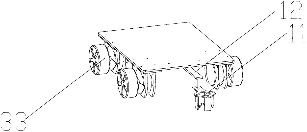
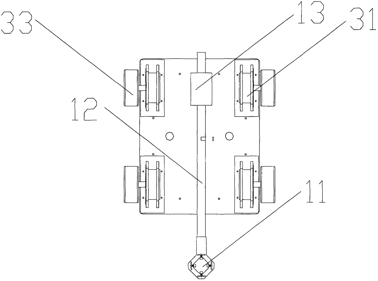
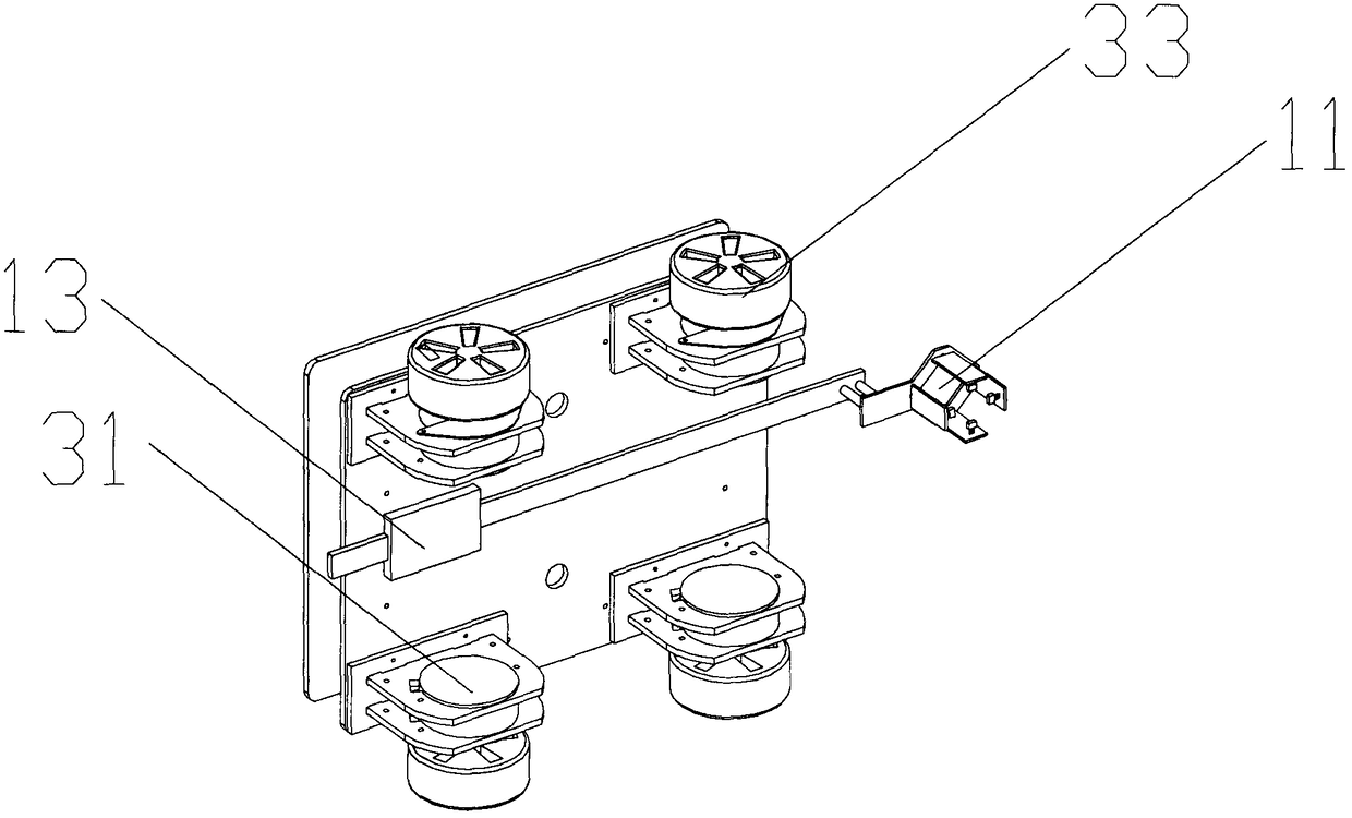
[0019] see Figure 1-4 , the present invention comprises positioning system 1, running gear 3; Walking gear 3 is made up of walking stepping motor 31, driving plate 32, walking wheel 33, and walking stepping motor 31 is connected with driving wheel 33 by driving plate 32.

[0020] see Figure 1-4 , the positioning system 1 is composed of a Hall probe 11, a telescopic mechanism 12, a mounting plate, and a stepping motor 13. The ste...


PUM


Abstract

The invention discloses a hall-positioning-system-based precise positioning apparatus and positioning method. The precise positioning apparatus is composed of a positioning system and a walking mechanism. A telescopic hall probe is selected to cooperate with the walking mechanism, so that precise millimeter-level positioning is realized; and a defect that the traditional geomagnetic positioning system only realizes geomagnetic reference point positioning can be overcome and precise positioning between adjacent geomagnetic reference points can be realized. The positioning system formed by the hall probe, a telescopic rod and a stepping motor is added and a positioning algorithm is realized based on an Arduino unit, so that precise positioning of any position between two geomagnetic reference points is realized without the need of improvement of the geomagnetic reference point density. Moreover, a precise turning effect with a 90-degree angle or an angle of a multiple of the 90 degrees is realized. The system structure is simple and positioning can be realized rapidly and precisely.

Description

technical field [0001] The invention relates to the technical field of positioning devices and methods, in particular to a precise positioning device and positioning method based on a Hall positioning system. Background technique [0002] The walking mechanism has exquisite structure, reliable control, stable operation, wide use and flexible application. Different end effectors can be installed to complete the work of workpiece handling in various shapes and states, which greatly reduces the heavy physical labor of human beings and improves the product quality. The quality stability and the automation level of the enterprise reduce the labor cost of the enterprise. The traditional moving mechanism uses the geomagnetism buried on the ground to mark the coordinates of the position, and uses the geomagnetic recognition sensor to accurately find and distinguish the existing The marked objects are calculated and analyzed by the control part, and the mechanical structure installed...

Claims


Application Information

Patent Timeline
Patent Type & Authority Patents(China)
IPC IPC(8): G05D1/02
CPCG05D1/0259G05D2201/0207
Inventor 徐知非
Owner 山东拓步教育科技有限公司
Why Eureka
Try Eureka