Vacuum circuit breaker

A technology of vacuum circuit breaker and vacuum interrupter, which is applied to high-voltage air circuit breakers, circuits, electrical components, etc., can solve the problems of delay in working hours and waste of capital costs.

Active Publication Date: 2014-04-02
北京交通大学长三角研究院
View PDF7 Cites 2 Cited by
  • Summary
  • Abstract
  • Description
  • Claims
  • Application Information

AI Technical Summary

Problems solved by technology

[0003] Existing vacuum circuit breakers generally include a static contact and a moving contact. The moving contact has a driving arm to drive up and down to realize the operation of opening and closing, and the driving plate is generally arranged perpendicular to the insulating pull rod. Using the existing structure, due to the need to transmit power between two vertical components, it is inevitable to cause relatively large stress concentration at the intersection of the two components, so in practice, it is often necessary to repair and replace this part, which not only delays working hours, but also causes waste of capital cost

Method used


Image

  • Vacuum circuit breaker
  • Vacuum circuit breaker
  • Vacuum circuit breaker

Examples


Embodiment 1

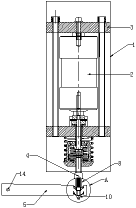
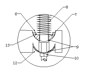
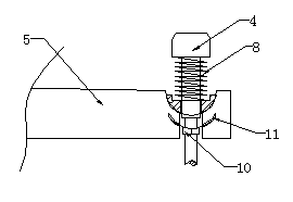
[0017] As shown in the figure, the vacuum circuit breaker of the present invention includes a housing 1 and a vacuum interrupter 2 arranged in the housing. The upper end of the vacuum interrupter 2 has a conductive plate 3 for conductive connection with the static contact. The moving contact at the lower end of the vacuum interrupter is connected to the push rod 4 located outside the housing through the moving contact part. The lower part of the push rod 4 has a drive plate 5 arranged perpendicular to the push rod, and one end of the drive plate 5 is installed on a fulcrum. And make the drive plate 5 swing around the fulcrum, the drive plate 5 upper end is provided with a hemispherical upper groove 6, the upper groove 6 is provided with a wear-resistant block 7 that cooperates with the upper groove 6, and the wear-resistant block 7 center is provided with For the central hole that the push rod passes through, a compression spring 8 is pressed between the drive plate 5 and the s...

Embodiment 2

[0020] As shown in the figure, the difference between this embodiment and Embodiment 1 is that the arc-shaped groove is a lower groove 12 of a hemispherical structure arranged on the rear end surface of the driving plate 5, and the wear-resistant block 5 and the limit nut 10 are installed in the upper concave groove respectively. In the groove 6 and the lower groove 12, this integral structure is easy to install and has better reliability.


PUM


Abstract

The invention discloses a vacuum circuit breaker, comprising a shell and a vacuum arc-extinguishing chamber, wherein the upper end of the vacuum arc-extinguishing chamber is provided with a current-conducting plate, a movable contact at the lower end of the vacuum arc-extinguishing chamber is connected with a push rod, the lower part of the push rod is provided with a driving plate, one end of the driving plate is arranged on supporting point, the upper end of the driving plate is provided with an upper groove, a wear-resistant block is arranged in the upper groove, the center of the wear-resistant block is provided with a central hole, a compressing spring is pressed between the driving plate and a step in the middle of the push rod, the rear end of the compressing spring is pressed on the front end face of the wear-resistant block, the lower half part of the driving plate is provided with an arc-shaped groove, the rear end of the push rod penetrates through piercing holes, the tail end of the push rod is provided with a limiting nut which is adapted to the arc-shaped groove in contour shape, the area of the limiting nut is smaller than the area of the arc-shaped groove, and the limiting nut is enabled to be positioned in the arc-shaped groove. After the structure is adopted, stress concentration caused by complete rigid vertical connection between the driving plate and the push rod traditionally is completely changed, and wear is effectively reduced.

Description

[0001] technical field [0002] The invention relates to a circuit breaker, in particular to a vacuum circuit breaker, which belongs to the technical field of electric power system power distribution equipment. Background technique [0003] Existing vacuum circuit breakers generally include a static contact and a moving contact. The moving contact has a driving arm to drive up and down to realize the operation of opening and closing, and the driving plate is generally arranged perpendicular to the insulating pull rod. Using the existing structure, due to the need to transmit power between two vertical components, it is inevitable to cause a relatively large stress concentration at the intersection of the two components, so in practice, it is often necessary to repair and replace this part of the component, which not only delays working hours, but also causes Waste of capital costs. Contents of the invention [0004] The technical problem to be solved by the presen...

Claims


Application Information

Patent Timeline
Patent Type & Authority Applications(China)
IPC IPC(8): H01H33/66H01H33/666
Inventor 张雷
Owner 北京交通大学长三角研究院
Why Eureka
Try Eureka