User equipment management method, device and system

A technology of user equipment and management methods, applied in the field of user equipment management methods, devices and systems, capable of solving problems such as MME pool migration failures

Active Publication Date: 2017-11-21
HUAWEI TECH CO LTD
View PDF5 Cites 0 Cited by
  • Summary
  • Abstract
  • Description
  • Claims
  • Application Information

AI Technical Summary

Problems solved by technology

[0008] In view of this, embodiments of the present invention provide a user equipment management method, device and system to solve the problem of migration failure of user equipment from the backup MME pool to the local MME pool

Method used


Image

  • User equipment management method, device and system
  • User equipment management method, device and system
  • User equipment management method, device and system

Examples


Embodiment 3

[0072] In this embodiment, whether the UE accessing the first MME is a local UE or a remotely migrated UE is distinguished by the information of the TA registered by the UE.

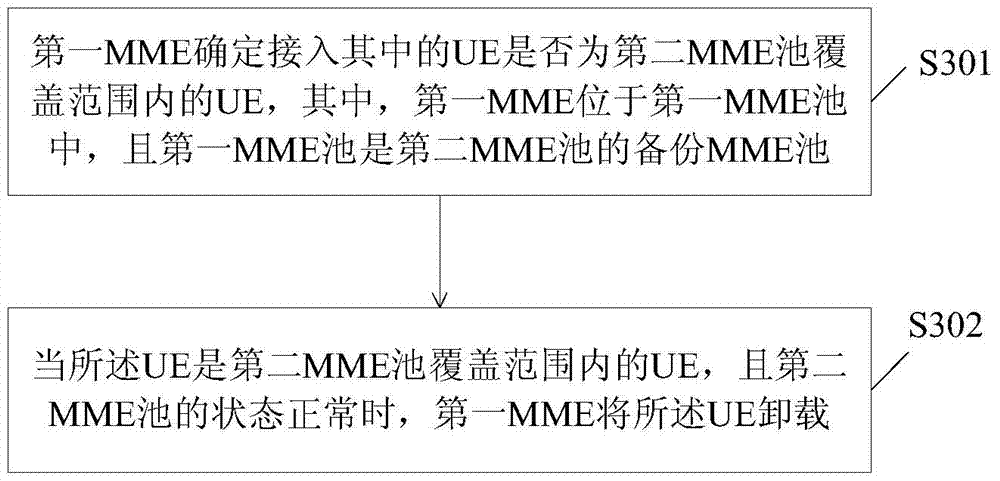
[0073] At this time, in the above step S301, the first MME determines whether the UE accessing the UE is a UE within the coverage of the second MME pool, including: determining whether the UE is the second MME pool according to the information of the TA registered by the UE. UEs within coverage.

[0074] Specifically, the UE may report the information of the registered TA to the first MME through the S1 interface message. For example, during the attach process, the UE reports the information of the registered TA to the first MME through an attach request (attach request) message. In addition, when the eNB establishes the S1-MME connection with the first MME, it may report the information of the TA where the eNB is located to the first MME, for example, the TA information is reported through the S1 Appli...

Embodiment 4

[0084] In this embodiment, when the first MME assigns an identifier to the UE, a flag bit is added to the identifier to distinguish whether the UE accessing the first MME is a local UE or a remotely migrated UE.

[0085] Specifically, when the UE is accessing the first MME, the first MME adds a flag bit to the user identity allocated to it to identify whether the UE is a user equipment within the coverage of the second MME pool, or It is used to identify whether the UE is accessed by the S1 link between the base station within the coverage of the second MME pool and itself. For example, if the UE accesses from the S1 link between the base station within the coverage of the second MME pool and itself, the flag bit is set to "1", otherwise, the flag bit is set to "0".

[0086] In this way, when the second MME pool returns to normal, the first MME can unload the UE migrated from the second MME pool according to the flag bit of the user identity of the user equipment accessing it....

Embodiment 5

[0102] In this embodiment, when allocating an identifier to the UE, the first MME may also use different identifier contents to distinguish whether the UE accessing the first MME is a local UE or a remotely migrated UE.

[0103] For example, the first MME may use the M-TMSI segment allocation method to allocate a special segment number to the UEs migrated from the second MME pool to distinguish whether the UEs accessing the first MME are local UEs or remote-migrated UEs .

[0104] For example, M-TMSI is 32bit, and can be 0 to 2 n Assigned to locally accessed UEs, where 0n+1 to 2 32-n It is allocated to the UE for remote relocation. In this way, the first MME can determine, according to the M-TMSI, whether the UE accessing the UE is a UE within the coverage of the second MME pool.

[0105] This embodiment may be combined with the first embodiment above. In this case, the above UE management method further includes:

[0106] When the UE accesses the first MME, a user identit...


PUM


Abstract

Embodiments of the present invention provide a UE management method, device and system. The method includes: the first MME determines whether the UE accessing the UE is a UE within the coverage of the second MME pool, where the first MME is located in the first MME pool. pool, and the first MME pool is the backup MME pool of the second MME pool; when the UE is a UE within the coverage of the second MME pool, and the status of the second MME pool is normal, the first MME will uninstall. It can be seen that when the MME in the first MME pool determines that the UE accessing it is from the second MME pool and the second MME pool returns to normal, it will offload the UE from the second MME pool. In this way, during the RRC establishment process, the UE will no longer carry the information of the MME in the first MME pool, and the eNB can select the MME in the second MME pool for the UE to establish an S1-MME connection according to its own policy, and the UE can return to the third MME pool. The second MME pool solves the problem of UE migration failure from the backup MME pool to the local MME pool.

Description

technical field [0001] Embodiments of the present invention relate to the field of communications technologies, and in particular, to a method, apparatus, and system for managing user equipment. Background technique [0002] In order to meet the challenges of wireless broadband technology and maintain the leading edge of the 3rd generation partnership project (3GPP) network, 3GPP has formulated the longterm evolution (LTE) plan for mobile communication networks, which is the guidance of this evolution plan. Next, a new mobile communication network architecture is defined, that is, the architecture of the Long Term Evolution / System Architecture Evolution (LTE / SAE) network system. [0003] Please refer to figure 1 , which is the architecture diagram of the prior art LTE / SAE network system. The LTE / SAE network system includes an evolved Node B (evolved Node B, eNB) (also called an evolved base station) 101 and a mobility management entity / serving gateway (MME / SGW, Mobility Ma...

Claims


Application Information

Patent Timeline
Patent Type & Authority Patents(China)
IPC IPC(8): H04W28/16
CPCH04W36/0022H04W8/065H04W88/14H04W92/045
Inventor 邓蕾
Owner HUAWEI TECH CO LTD
Why Eureka
Try Eureka