
Vortex oscillator

A vortex oscillator and plasticity technology, which is applied in shaking/oscillating/vibrating mixers, chemical instruments and methods, dissolution and other directions, can solve problems such as poor mixing effect, hinder stability, etc., and achieve low manufacturing cost and use. Convenience and simple structure

Active Publication Date: 2014-04-09
北京达博创新科技开发有限公司
View PDF5 Cites 12 Cited by
  • Summary
  • Abstract
  • Description
  • Claims
  • Application Information

AI Technical Summary

Problems solved by technology

[0002] The vortex oscillator in the prior art uses a spring to limit the rotation of the sample block. Due to the elastic deformation of the spring, the sample will not only revolve around the axis, but also periodically oscillate. The stability of the vortex formed by the liquid in the tube in the block, resulting in poor mixing

Method used


Image

  • Vortex oscillator
  • Vortex oscillator
  • Vortex oscillator

Examples


Embodiment Construction

[0021] In order to make the technical problems, technical solutions and beneficial effects solved by the present invention clearer, the present invention will be further described in detail below in conjunction with the accompanying drawings and embodiments. It should be understood that the specific embodiments described here are only used to explain the present invention, not to limit the present invention.

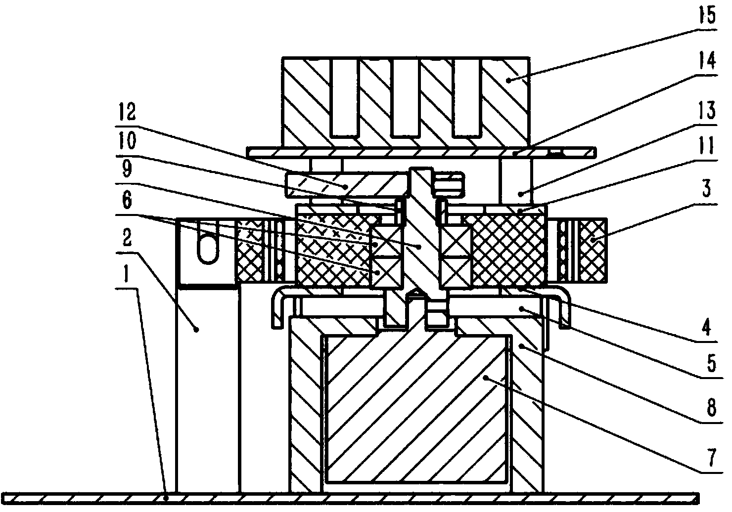
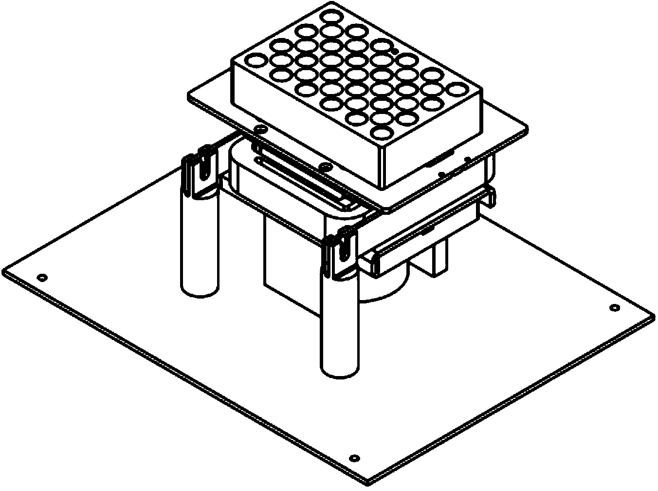
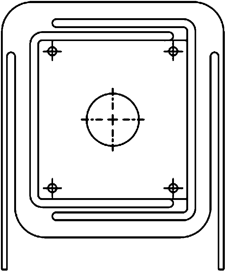
[0022] Such as Figure 1 to Figure 4 A vortex oscillator shown includes a motor 7, a base of the motor 7, an eccentric shaft 9, a plastic deformation control bracket 3, a bearing 6, a nut 10 on the shaft, a sample block 15, a sample block support plate 14, a pillar 2 and an isolation Column 13; the motor 7 is fixed on the base of the motor 7, and the rotating shaft of the motor 7 is in transmission connection with the eccentric shaft 9; the plastic deformation control bracket 3 is installed on the eccentric shaft 9 through the bearing 6 , and the plastic deformation con...


PUM


Abstract

The invention relates to a vortex oscillator. A motor is fixed on a motor base, and a rotating shaft of the motor is in transmission connection with an eccentric shaft; a plastically deformable control support is mounted on the eccentric shaft through a bearing, and the plastically deformable control support and the eccentric shaft can rotate relative to each other; an upper support plate and a lower support plate are arranged above and below the plastically deformable control support respectively, an upper counterweight is arranged at the top end of the eccentric shaft, and a lower counterweight is arranged on the lower support plate; a sample block is arranged on a sample block support plate, and the sample block support plate is arranged on the upper support plate through an isolation column; the bottom of a pillar and the motor base are relatively fixed, and the top of the pillar is connected with the plastically deformable control support. The vortex oscillator provided by the invention can effectively limit the autorotation motion of the sample block and ensure the stable revolution motion of the sample block, and enables a reagent placed in a test tube in the sample block to produce a stable vortex so as to achieve an excellent uniform mixing effect.

Description

technical field [0001] The invention relates to the technical field of mechanical structures, in particular to a vortex oscillator. Background technique [0002] The vortex oscillator in the prior art uses a spring to limit the rotation of the sample block. Due to the elastic deformation of the spring, the sample will not only revolve around the axis, but also periodically oscillate. The stability of the vortex formed by the liquid in the test tube in the block, resulting in poor mixing. Contents of the invention [0003] The purpose of the present invention is to design a novel vortex oscillator to solve the above problems. [0004] In order to achieve the above object, the technical scheme adopted in the present invention is as follows: [0005] A vortex oscillator, including a motor, a motor base, an eccentric shaft, a plastic deformation control bracket, a bearing, a nut on the shaft, a sample block, a sample block support plate, a pillar and an isolation column; ...

Claims


Application Information

Patent Timeline
Patent Type & Authority Applications(China)
IPC IPC(8): B01F11/00
Inventor 刘越赵乘程瑶曹少军董晶
Owner 北京达博创新科技开发有限公司
Learn More