pumps, especially pneumatic pumps

A pump chamber and spring chamber technology, applied to pumps, can solve the problems of cost, spring loading into the pump, assembly technology cost, etc.

Active Publication Date: 2016-10-26
ALFMEIER PRAZISION BAUGRUPPEN & SYSTLOSUNGEN
View PDF9 Cites 0 Cited by
  • Summary
  • Abstract
  • Description
  • Claims
  • Application Information

AI Technical Summary

Problems solved by technology

Measures have been taken so far to use springs of different strengths when assembling the pump, but this is associated with corresponding outlay, logistical and also assembly-technical outlay
There is also the risk of the wrong spring being inserted into the pump during assembly

Method used


Image

  • pumps, especially pneumatic pumps
  • pumps, especially pneumatic pumps
  • pumps, especially pneumatic pumps

Examples


Embodiment Construction

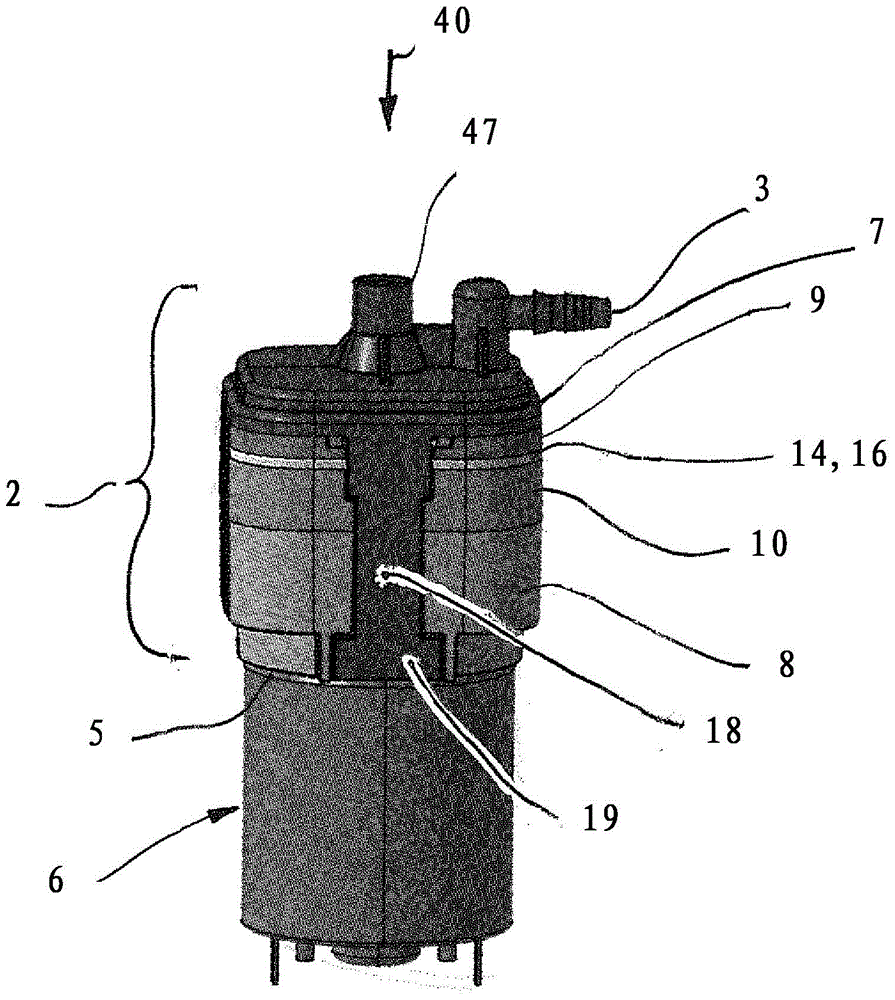
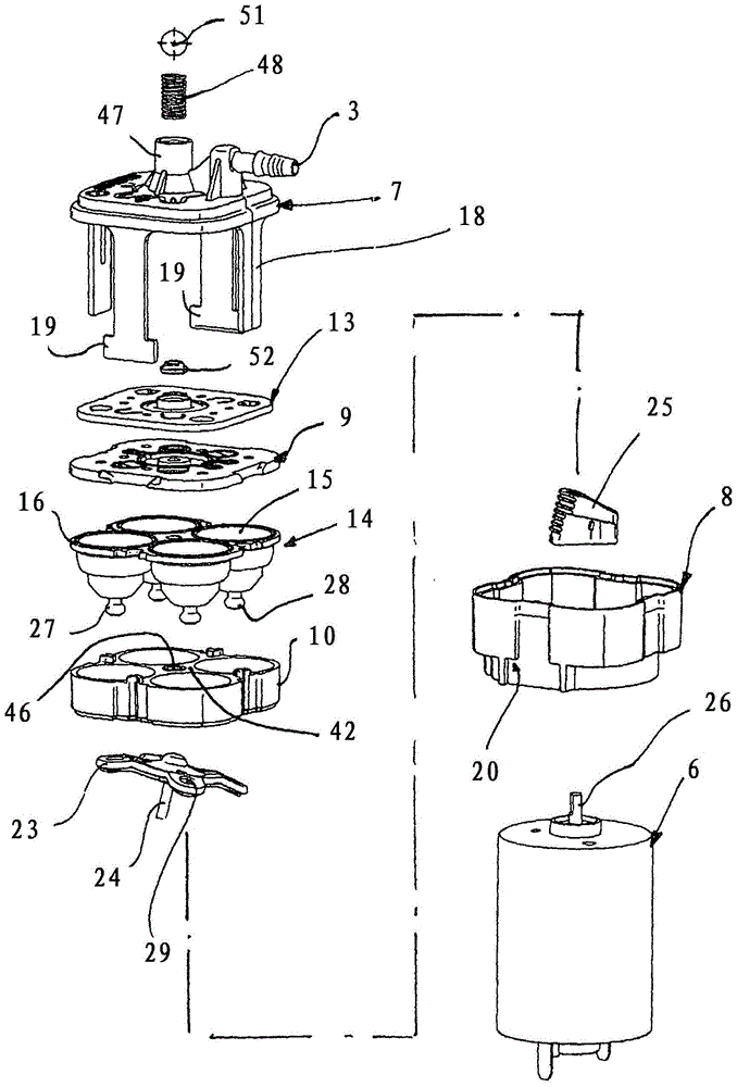
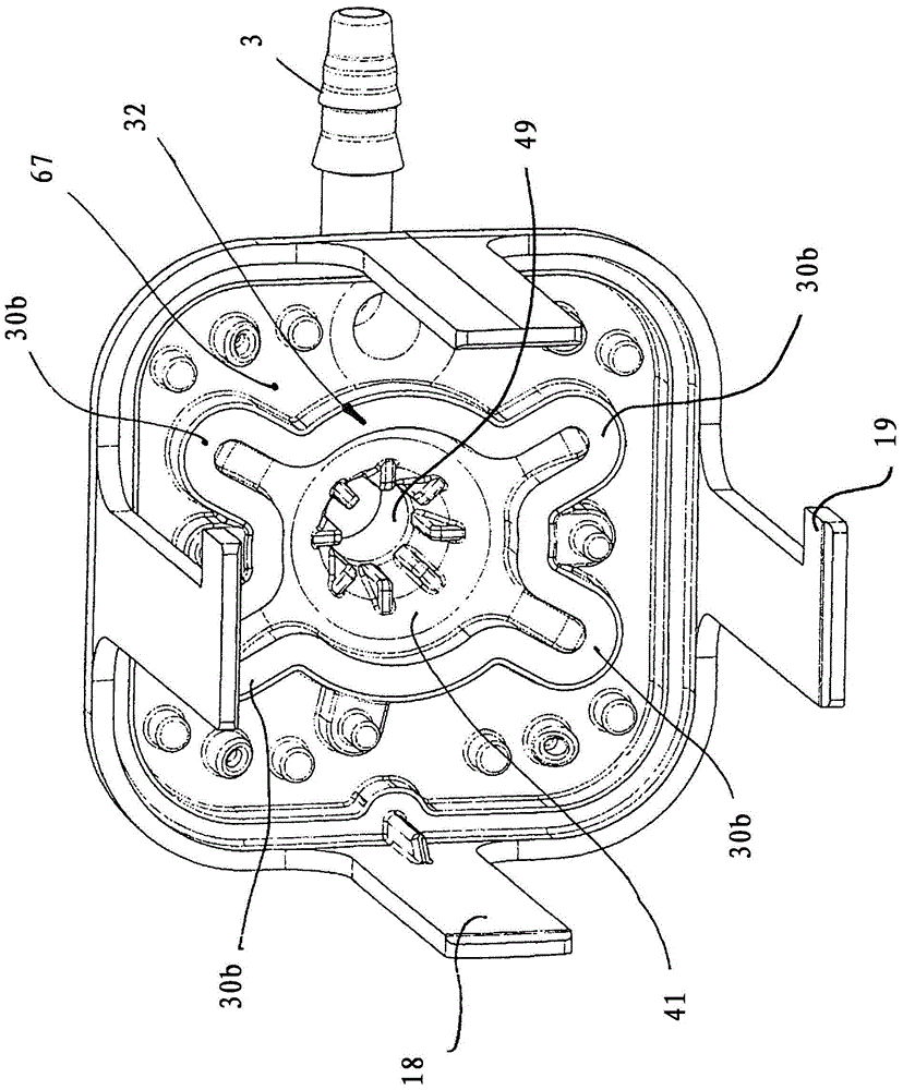
[0023] The invention is explained by way of example for a pneumatic pump, wherein the described embodiment also applies to pumps for liquids. The pump 1 shown in the figure is intended to be installed in a vehicle seat and to fill a seat airbag in order to modify the contour of the vehicle seat, for example in a seating area or a reclining area. The pump 1 comprises a housing 2, in particular made of plastic, onto which a discharge connection 3 is integrally formed. The side of the housing 2 which bears the outlet connection 3 is referred to below as the upper side 4 . A motor 6 , in particular an electric motor, is flanged to the underside 5 of the housing 2 . The housing 2 comprises an upper part 7 and a lower part 8 , wherein the upper part 7 supports the connection socket 3 and forms the upper side 4 . Two plate-shaped supports, an upper support 9 and a lower support 10 , are sandwiched between the upper part 7 and the lower part 8 . A plate-shaped valve membrane 13 mad...


PUM


Abstract

The invention relates to a pump comprising a housing (2), at least one pump chamber (15), an inlet valve (30) with a valve element (30a) controlling the inlet opening (30c), an inlet valve (30) with a controlling outlet opening ( 33c) the discharge valve (33) of the valve element (33a) and a pressure relief valve (43) as well as a spring chamber (49) which controls the pressure relief opening (43c) in the closing direction (31) Valve element (43a) loaded by spring element (48), said spring chamber (49) receiving the spring element. A stop element (51) adjustable in the closing direction (31) is arranged in the spring chamber (49), accessible from the outside of the housing, the spring element (48) is supported with its end pointing counter to the closing direction on the stop element.

Description

[0001] This application is a divisional application of an invention patent application named "pump, especially a pneumatic pump", the international application date is September 3, 2012, the international application number is PCT / EP2012 / 067126, and the national application number is 201280027521.5. technical field [0002] The invention relates to a pump, especially a pneumatic pump. Pneumatic pumps are used in the motor vehicle sector, for example, to fill airbags present in vehicle seats with which the contour of the seating area or reclining area of ​​the seat can be changed. For example, the pump for this purpose has at least one pump chamber for this purpose. By expanding and reducing the chamber volume by means of a drive unit, air is drawn from the surroundings into the pump chamber when the volume is enlarged and air is forced out of the pump chamber when the volume is reduced. To control the corresponding air flow, the pump has an inlet valve with a valve element co...

Claims


Application Information

Patent Timeline
Patent Type & Authority Patents(China)
IPC IPC(8): F04B43/02F04B45/04F04B43/00B60N2/44B60N2/90
CPCF04B43/0045F04B45/045F04B49/035F04B49/22
Inventor E·德夫勒R·盖尔曼
Owner ALFMEIER PRAZISION BAUGRUPPEN & SYSTLOSUNGEN
Why Eureka
Try Eureka