
Self-operated pressure regulator

A pressure-regulating, self-operated technology, applied in pipeline systems, mechanical equipment, gas/liquid distribution and storage, etc., can solve the problems of narrow application range, easy aging of the diaphragm, easy rupture of the diaphragm, etc., to achieve convenient operation and use Effects of long life and broadened application range

Inactive Publication Date: 2014-04-09
青岛恒邦机电科技有限公司
View PDF4 Cites 4 Cited by
  • Summary
  • Abstract
  • Description
  • Claims
  • Application Information

AI Technical Summary

Problems solved by technology

The disadvantage of using the diaphragm form is that the diaphragm is easy to age and the scope of application is narrow; because when the diaphragm bears a pressure of 1.0Mpa and the medium pressure exceeds 1.0Mpa, the diaphragm is easy to break

Method used


Image

  • Self-operated pressure regulator

Examples


Embodiment Construction

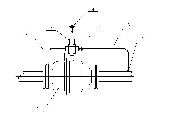
[0012] In the accompanying drawings, the self-operated pressure regulating valve is composed of a pressure taking pipe 1 before the valve, a control valve 2, a pilot 3, a regulating valve 4, a throttle valve 5, a pressure taking pipe 6 after the valve and a pressure taking point 7 after the valve. Among them, one end of the pre-valve pressure pipe 1 is connected to the control valve 2, the other end of the pre-valve pressure pipe 1 is connected to the front end of the pilot 3, the regulating valve 4 is connected to the upper end of the pilot 3, and the rear end of the pilot 3 The throttle valve 5 is connected to one end of the pressure-taking pipe 6 after the valve, and the other end of the pressure-taking pipe 6 after the valve is connected to the pressure-taking point 7 after the valve.

[0013] The control valve (2) is provided with a pressure chamber inside the valve, and the pressure chamber inside the valve is in the form of a piston.

[0014] Working principle of the pr...


PUM


Abstract

The invention discloses a self-operated pressure regulator which can eliminate membrane aging and widen the application range of a valve. The self-operated pressure regulator is characterized by comprising an upstream pressure tapping pipe (1), a control valve (2), a director (3), a regulating valve (4), a throttling valve (5), a downstream pressure tapping pipe (6) and a downstream pressure tapping point (7), one end of the upstream pressure tapping pipe (1) is connected with the control valve (2), the other end of the upstream pressure tapping pipe (1) is connected with the front end of the director (3), the regulating valve (4) is connected with the upper end of the director (3), the rear end of the director (3) is connected with one end of the downstream pressure tapping pipe (6) through the throttling valve (5), and the other end of the downstream pressure tapping pipe (6) is connected with the downstream pressure tapping point (7).

Description

technical field [0001] The invention relates to the field of regulating valve devices, in particular to a self-operated pressure regulating valve capable of eliminating diaphragm aging and widening the application range of the valve. Background technique [0002] As we all know, the internal pressure chamber of the traditional self-operated pressure regulating valve is in the form of a diaphragm. The disadvantage of using the diaphragm form is that the diaphragm is easy to age and the scope of application is narrow; because when the diaphragm bears a pressure of 1.0Mpa and the medium pressure exceeds 1.0Mpa, the diaphragm is easily broken. Contents of the invention [0003] The purpose of the present invention is to provide a self-operated pressure regulating valve which eliminates the aging of the diaphragm and widens the application range of the valve. [0004] In order to solve the existing problems of the background technology, the present invention adopts the...

Claims


Application Information

Patent Timeline
Patent Type & Authority Applications(China)
IPC IPC(8): F17D3/01
Inventor 高崧董国良
Owner 青岛恒邦机电科技有限公司
Learn More